What Makes a Ceramic Launder Better Than Traditional Refractory Troughs?
Not all molten aluminum launders are equal. Older cast houses often run steel-shell troughs with hand-applied refractory coatings—technology that worked well enough thirty years ago but struggles to meet today’s alloy quality demands, especially for precision applications like aerospace castings, automotive structural components, and medium-micron aluminum foil rolling stock.
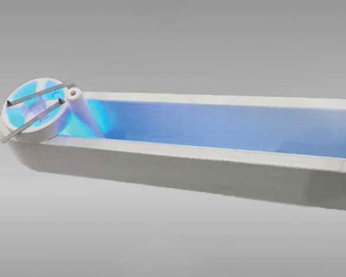
Our ceramic launder uses a new high-silicon molten material molding technology that produces a monolithic, dimensionally precise trough body. Unlike rammed or troweled refractory linings that develop surface irregularities and micro-cracks after a few dozen heats, a precision-molded ceramic launder starts with a smooth, uniform surface—and keeps it across hundreds of casting campaigns.
The high-silicon composition delivers a specific combination of properties that matter in practice:
- Non-stick aluminum performance — Molten aluminum doesn’t wet the surface easily, which means less skull buildup, easier cleaning, and fewer oxide inclusions re-entering the melt
- Corrosion resistance — Stands up to prolonged contact with common wrought and foundry alloys without significant chemical degradation
- No contamination to aluminum liquid — The launder body doesn’t shed particles or react with the melt, preserving metal purity through the transfer path
- Dual function: conveying and heat preservation — The low thermal conductivity of the high-silicon matrix acts as a built-in insulation layer, reducing temperature drop without requiring massive external insulation
That last point is worth emphasizing. Every degree of heat loss between furnace and mold means either higher tap temperatures (more energy, more hydrogen absorption, more dross) or out-of-spec metal at the casting station. A well-designed ceramic launder system holds temperature drop to 1–3 °C per linear meter under steady-state flow with covers in place. Without covers, you’re looking at 8–15 °C/m—and in outdoor transfer sections, even worse.
Product Specifications
Our standard ceramic launder range covers most aluminum casting configurations, from short transfer runs in smaller foundries to extended multi-section systems in large-scale DC casting operations.
Dimensional Specifications
| Item | Length Range | Flow Control Complement | Special Specifications |
|---|---|---|---|
| Standard ceramic launder | 200–3,000 mm | According to customer drawings | Custom profiles, junction boxes, and distribution sections available per drawing |
Standard lengths cover the majority of primary and secondary aluminum casting layouts. Custom lengths and cross-sections are manufactured to order with typical lead times of 3–5 weeks.
Technical Parameters
| Property | Unit | Value Range |
|---|---|---|
| Bulk density | g/cm³ | 1.0–1.4 |
| Rupture modulus (816 °C) | MPa | 10.5–11.8 |
| Thermal expansivity (680 °C) | K⁻¹ | 1.23 × 10⁻⁶ |
| Thermal conductivity (540 °C) | W/(K·m) | 0.5–0.65 |
| Maximum operating temperature | °C | 1,260 |
Technical parameters measured per ASTM C133 (rupture modulus) and ASTM E228 (thermal expansion) test methods. Values represent typical production lot ranges; individual test certificates available upon request.
That thermal expansivity number—1.23 × 10⁻⁶ K⁻¹—deserves attention. It’s extremely low, roughly on par with fused silica, which is precisely why these launders handle repeated thermal cycling without the cracking that plagues higher-expansion refractory materials. You can preheat, run a full campaign, let it cool, and do it again hundreds of times without accumulated thermal fatigue damage.
The low density (1.0–1.4 g/cm³) also means practical handling advantages. A 1,500 mm launder section is light enough for two workers to position without a crane—significantly reducing changeover time compared to heavy steel-shell alternatives.
Why Does Non-Stick Performance Matter So Much in Aluminum Launders?
If you’ve ever spent a shift chipping frozen aluminum skull out of a launder trough, you already know the answer. But the real cost goes beyond labor hours.
Every time aluminum wets and bonds to the launder surface, you lose recoverable metal. At current LME aluminum prices hovering around $2,400/tonne (mid-2024), a cast house running 30,000 tonnes per year with a 2.5% dross rate is losing roughly $1.8 million annually in metal value—and a significant portion of that dross forms inside the transfer system itself.
Worse, aggressive mechanical cleaning of stuck aluminum damages the launder surface, creating rougher texture that promotes even more sticking on the next campaign. It’s a degradation cycle that accelerates until the launder needs replacement far earlier than its material properties would otherwise allow.
The high-silicon molded ceramic composition we use is specifically formulated to resist aluminum wetting. The surface stays smooth across repeated use, cleaning reduces to simple brush-out or light scraping, and the molten aluminum launder liner can be used multiple times without the relining labor that steel-shell systems require.
Surface Adhesion Comparison: Ceramic vs. Conventional Refractory Launders
| Launder Type | Typical Surface Roughness (Ra) | Aluminum Wetting Angle | Cleaning Effort | Skull Loss per Campaign |
|---|---|---|---|---|
| High-silicon ceramic (molded) | < 3.2 μm | > 140° (non-wetting) | Light brush/scrape | < 0.3 kg/m |
| Cast refractory lining | 10–30 μm | 90–120° | Moderate chipping | 0.8–2.0 kg/m |
| Hand-applied refractory coating | 25–60 μm | 70–100° | Heavy chipping/grinding | 2.0–5.0 kg/m |
Wetting angle measurements conducted at 720 °C with 6063 alloy per sessile drop method. Skull loss data compiled from field measurements across multiple casting facilities. Higher wetting angle indicates superior non-stick behavior.
What Applications Require High-Quality Ceramic Launder Systems?
The refractory launder is suitable across the full spectrum of aluminum processing, but it becomes truly essential—not just beneficial—in applications where metal cleanliness and temperature consistency directly determine product viability:
Aerospace precision castings — Investment cast turbine blades, structural brackets, and flight-critical components have near-zero tolerance for oxide inclusions. The transfer path from furnace to mold must preserve the cleanliness achieved by upstream degassing and filtration systems.
Automotive structural components — As automakers shift toward aluminum-intensive body structures, inclusion specifications have tightened dramatically. A single oxide film in a safety-critical casting means rejection.
Rolling stock for medium-micron aluminum foil — Foil rolling amplifies every defect in the original cast strip. Pinhole defects traced back to inclusions from the transfer system are a persistent quality issue in foil production. Clean launders are non-negotiable here.
DC-cast extrusion billets — Surface quality, macrosegregation, and hot cracking sensitivity all respond to the temperature uniformity delivered by the transfer system.
For standard commodity casting, cheaper launder options might survive. But if your customers are sending back PoDFA inclusion reports and asking pointed questions about your melt handling practices, upgrading the launder system is usually the fastest return-on-investment improvement available. It integrates directly with ceramic foam filter boxes and inline treatment units to form a complete quality chain.
How Should You Install a Ceramic Launder System?
Proper installation determines whether your launder delivers its full service life or fails prematurely. Based on field experience across hundreds of installations, here are the steps that matter most.
Step 1: Alignment and Support
Install the ceramic launder sections corresponding to the drawing structure. Each section must be supported continuously along its full length—never just at the ends. Use adjustable steel cradles with ceramic fiber blanket padding between the cradle and the launder body to prevent point loading.
Check level with a precision instrument. A consistent 1–2% downward slope toward the casting end ensures reliable gravity flow and complete drainage at the end of the campaign. Ensure that the movable launder is clean, free of damage, and that joints are seamless—any gap or crack at a joint is a potential leak point.
Step 2: Joint Sealing
Our launder sections feature interlocking profiles at each joint. Seal the interfaces with high-temperature ceramic fiber gasket rope. Don’t over-compress the gasket—firm contact is sufficient. Excessive clamping force deforms the gasket and reduces its sealing effectiveness.
Step 3: Preheating — The Most Critical Step
This is where launders live or die. Ceramic materials, no matter how good their thermal shock resistance, need controlled preheating before molten metal contact. Rushing this step is the single most common cause of premature launder failure.
With electric heating elements (recommended):
Warm up the installed launder evenly. Heat up at a uniform speed over 1–2 hours to remove adsorbed crystal water and bring the launder close to casting temperature. Electric heating provides precise, uniform temperature control.
Without electric heating (flame preheating):
When electric baking conditions are not available, flame preheating works—but requires more care. Two critical controls:
- Control the flame temperature — Start with weak flame (red, soft flame), progress to medium flame (yellow), then strong flame (blue-white) only in the final stage
- Prevent direct flame impingement — Never aim the burner flame directly at the launder surface. Direct roasting causes severe local temperature gradients that easily crack or burst the liner. Keep the flame moving, use diffused heat, and maintain a minimum 150 mm standoff distance
Recommended preheating schedule:
| Phase | Temperature Range | Heating Rate | Duration | Purpose |
|---|---|---|---|---|
| Initial drying | Ambient → 300 °C | ≤ 50 °C/hour | ~5–6 hours | Remove physically adsorbed moisture |
| Intermediate hold | 300 °C | Hold | 30 minutes | Equalize temperature throughout section |
| Ramp to operating temp | 300 → 500–600 °C | ≤ 80 °C/hour | ~3–4 hours | Bring to near-casting temperature |
| Final soak | 500–600 °C | Hold | 15–20 minutes | Confirm uniform temperature before metal contact |
Preheating protocol based on manufacturer recommendations for high-silicon fused silica ceramic launders. Faster heating rates may be acceptable for daily restart from warm idle (150–200 °C) but should never exceed 100 °C/hour. Reference: AdTech installation guidelines and general refractory preheating practices per The American Ceramic Society technical literature.
Following this protocol consistently is what separates a launder that lasts 40 campaigns from one that lasts 400. It takes discipline, especially under production pressure when someone wants to “just get it hot and start casting.” Don’t.
Real Case: Rebuilding a Transfer System for a Russian Billet Caster
In late 2021, a billet casting operation in Krasnoyarsk, Russia, reached out about chronic problems on their 6xxx-series extrusion billet line. The facility produced approximately 28,000 tonnes per year of 6063 and 6005A alloy billets, primarily for the domestic construction market, with growing export demand requiring tighter quality certification.
What the Production Line Looked Like Before
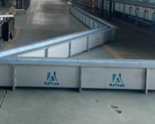
The existing transfer system was a patchwork built up over years of incremental modifications. The main transfer path—roughly 14 meters from tilting furnace to casting table—used a combination of:
- Original steel-shell launders with rammed alumina-silicate lining (installed ~2012, relined multiple times)
- Two replacement sections from a local refractory supplier, slightly different internal dimensions
- Improvised junction pieces fabricated on-site from castable refractory
Temperature measurements showed ±14 °C variation between the online degassing unit outlet and the casting table inlet. Dross generation was running at approximately 3.1% of throughput. Most critically, PoDFA inclusion analysis on finished billets was consistently failing to meet the K1-10 standard required by their European export customers—oxide film counts were roughly double the acceptable limit.
The plant’s quality manager put it bluntly during our first call: “We’re spending more time fixing the transfer system than running it. And we’re losing an export contract because of inclusions we can see on the PoDFA samples.”
What Changed
After reviewing the plant layout drawings and thermal profile data, we shipped a complete replacement system:
- 12 standard ceramic launder sections (1,200 mm and 1,500 mm lengths, 180 mm internal width) covering the full transfer distance
- 2 distribution junction boxes for the two-strand casting configuration
- Full set of insulating ceramic fiber covers with lift-off inspection ports
- 6 ceramic foam filter plates (50 ppi, 17-inch square) as initial consumable stock for the existing filter box unit
Our technical team provided remote installation guidance via video conference over three days, working with the plant’s maintenance crew to get alignment, joint sealing, and preheating procedures right the first time. Total installation downtime was four days—they had scheduled a week.
Results After Six Months of Operation
The numbers told the story clearly:
- Temperature variation across the transfer system dropped to ±3.5 °C under steady-state casting
- Dross generation fell from 3.1% to 1.3% of throughput—saving an estimated $165,000/year in metal value at prevailing prices
- PoDFA inclusion counts dropped below the K1-10 threshold on every sample tested from the third campaign onward
- Zero launder-related production stoppages over the first six months (compared to four unplanned stops in the six months prior)
- The European export contract was secured
The customer placed a follow-up order in mid-2022 for ceramic launder sections and degassing rotor consumables to support a planned capacity expansion. As of early 2024, the original launder sections have exceeded 280 campaigns with no measurable performance degradation—well on track to deliver the 400+ campaign life that the material is capable of achieving with proper care.
If your project requires the use of ceramic launder, you can contact us for a free quote.
How Often Should Ceramic Launders Be Replaced?
This is the practical cost question every purchasing manager asks, and the honest answer is: it depends almost entirely on how you treat them.
The ceramic material itself has a long potential service life. Our high-silicon molded launders routinely achieve 200–400+ casting campaigns when preheating and cleaning protocols are followed consistently. We’ve had customers push past 500 campaigns on original sections, though at that point we recommend careful inspection for micro-crack development and surface degradation.
The factors that shorten service life are predictable and preventable:
- Thermal shock from improper preheating — The number one killer. One cold-start without proper preheat can crack a launder that would have otherwise lasted years.
- Aggressive mechanical cleaning — Hardened steel chisels and impact tools damage the surface glaze. Use gentle scraping, pneumatic descaling, or controlled burn-out cleaning instead.
- High-magnesium alloy exposure — Alloys above ~4% Mg (5xxx series) are more chemically aggressive toward silica-based refractories. For heavy 5xxx production, discuss material options with our technical team.
- Excessive thermal cycling frequency — Continuous casting operations are easier on launders than intermittent batch operations with full cool-down between each campaign.
When a launder section does reach end of life, replacement is fast. The modular design means you swap individual sections rather than rebuilding the entire system—typically a 2–3 hour job per section including alignment and gasket sealing. Compare that to the 1–2 day reline cycle required for steel-shell troughs and the operational advantage becomes obvious.
Complete Transfer System Design and Custom Engineering
Refractory troughs are one of our primary product offerings, and the range extends well beyond standard catalog shapes. There are a number of shapes and sizes available, and we have experience producing a large variety of different configurations for customers in different industries—primary smelters, secondary remelters, rolling mills, and precision foundries.
We can often provide insight into the causes of premature launder failures in existing systems and offer material or design change recommendations to correct the problems. In many cases, a dimensional mismatch between launder sections—different suppliers, different eras, slightly different internal profiles—creates turbulence points and dead zones where dross accumulates and inclusions form. Standardizing on a single, properly engineered system eliminates these problems at the source.
Our capabilities include:
- Standard launder sections in lengths from 200 mm to 3,000 mm
- Custom cross-section profiles to match specific flow rate and metal level requirements
- Distribution launders and junction boxes for multi-strand casting
- Integration with ceramic foam filter systems and inline degassing units
- Complete turnkey launder system design for new casting line installations
- Retrofit design for upgrading existing transfer paths
For projects requiring full custom engineering, we work from customer layout drawings to develop a complete launder system design—including thermal modeling, flow analysis, and support structure specifications. We’ve provided customers with complete refractory launder lines as well as designed and built entirely new custom systems from concept through commissioning support.
Key Advantages at a Glance
- Good thermal insulation performance, low density, good non-stick aluminum behavior, and good operability in casting and rolling applications
- High-silicon molten material molding process delivers high dimensional accuracy and consistent surface quality
- Can be used repeatedly across multiple campaigns—the surface stays smooth and functional far longer than conventional refractory linings
- Proven across demanding applications: aviation, transportation, precision castings, and rolling stock for medium-micron aluminum foil
- Modular design enables fast section replacement without system-wide rebuilds
- Compatible with the full range of molten aluminum processing equipment for integrated system solutions
FAQ
1. What is a ceramic launder used for?
A ceramic launder is used to transfer molten aluminum safely from the furnace to the casting or rolling line while reducing heat loss and contamination.
2. Why choose a ceramic launder instead of a metal trough?
A ceramic launder offers better thermal insulation, resists corrosion, and has a non-stick aluminum surface that helps reduce dross buildup.
3. Can the ceramic launder be reused?
Yes. The launder liner can be used multiple times when it is properly installed, preheated, and maintained.
4. Is the ceramic launder suitable for aluminum alloys?
Yes. It is mainly used for molten aluminum and aluminum alloy applications, including precision castings, transportation parts, and foil rolling lines.
5. Does the ceramic launder react with molten aluminum?
No. It has good non-stick aluminum performance and does not pollute the molten aluminum during transfer.
6. What is the maximum operating temperature?
The maximum operating temperature is 1260°C.
7. How should a ceramic launder be preheated?
It should be heated evenly and gradually before use. If flame heating is used, avoid direct flame contact with the liner surface.
8. What lengths are available?
Standard lengths range from 200 mm to 3000 mm, and custom sizes can be made according to drawings.
9. Can you make custom refractory launders?
Yes. Custom shapes, flow control complements, and special specifications can all be produced based on customer drawings.
10. What are the main advantages of this ceramic launder?
Its main advantages are low density, good heat preservation, high dimensional accuracy, smooth surface, corrosion resistance, and strong non-stick aluminum performance.