In aluminum casting, maintaining consistent melt flow and achieving defect-free products starts at the tip of the pouring system. The ceramic casting tip is a small but critical component that directly impacts metal cleanliness, flow rate, and mold fill quality. Choosing the right tip, understanding its material, and optimizing its usage can dramatically improve casting yield and reduce costly defects such as porosity and oxide inclusions, which can be minimized using high-quality aluminum purification materials. Using a properly coated tip with Boron Nitride (BN) can further prevent molten metal adhesion, ensuring a smoother metal flow and reducing turbulence.
In this article, we explore professional insights, data-driven recommendations, and long-term operational experiences to help foundries get the most from their ceramic casting tips.
What is a Ceramic Casting Tip and Why Does It Matter?
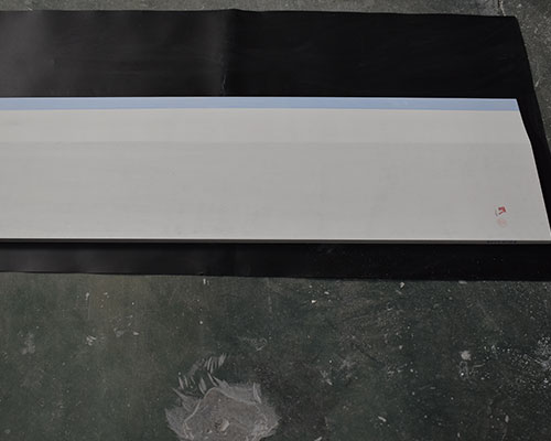
A ceramic casting tip is a refractory nozzle installed at the end of a pouring system to guide molten aluminum into molds. Compared with traditional metal nozzles, ceramic tips offer:
- Higher thermal stability – resist deformation and erosion at elevated temperatures up to 800°C.
- Smoother metal flow – reduces turbulence, limiting oxide formation.
- Extended service life – non-wetting surfaces minimize metal adhesion.
Industry Insight: According to ASM Metals Handbook, proper nozzle selection can reduce oxide inclusions by up to 30% in continuous casting processes.
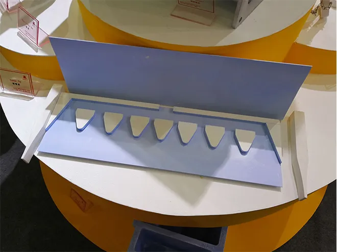
Key Components of a Ceramic Casting Tip System
A typical ceramic caster tip system includes the caster tip, spacer, and hard/soft ears. These components work together to control metal flow and ensure uniform gauge. The hard or soft ears also interact with the flow control system of your line, helping to absorb thermal stresses and vibrations while stabilizing pouring speed and distribution.
| Component | Location / Placement | Primary Function | Operational Notes |
|---|---|---|---|
| Caster Tip | End of the twin-roll caster headbox, in direct contact with molten aluminum | Guides and controls metal flow into the rolls; reduces turbulence and oxide formation | Ensure tip surface is smooth; proper preheating prevents cracking |
| Spacer | Between the caster tip and headbox mounting surface | Maintains uniform gap; ensures correct metal distribution | Must be positioned evenly; prevents warping or uneven gauge |
| Hard/Soft Ear | Side extensions on the tip assembly | Absorb thermal stress and vibrations; secure tip in headbox | Choose hard or soft ear depending on pouring speed and thermal load; soft ears offer cushioning, hard ears provide stability |
This table reflects typical twin-roll caster configurations and practical experience from multiple aluminum foundries.
Fixed-size Specifications of Caster Tip(mm)
| Length | Width | Tip thickness | R radius | Shape |
|---|---|---|---|---|
| 200-2300 | 50-600 | 1.6-10 | Data fixed value | Chamber/Horizontal |
These are AdTech’s standard caster tip specifications. For customized dimensions tailored to your production line, please contact us
How Do Ceramic Casting Tips Affect Melt Quality?
Poor tip condition can create turbulence, trapping air or oxide inclusions in the melt. To control these effects, combining a well-designed tip with a flow control system ensures laminar metal flow, while degassing unit can remove dissolved hydrogen and reduce porosity. Together with the right tip coating, these measures significantly enhance cast quality.
| Common Defect | Potential Tip-Related Cause | Corrective Approach |
|---|---|---|
| Porosity | Turbulent pouring; uneven flow | Select smooth ceramic tips and optimize tip diameter |
| Cold Shuts | Uneven filling; delayed solidification | Adjust tip diameter and pouring rate to match alloy viscosity |
| Oxide Inclusions | Metal splashing or oxidation at the tip | Use high-quality ceramic tips with polished surface |
Table compiled from operational data in European and North American aluminum foundries.
How Can You Identify and Fix Common Ceramic Tip-Related Casting Defects?
Poor tip condition is responsible for a substantial portion of casting defects. Recognizing the connection between tip performance and defect occurrence helps troubleshoot problems efficiently.
| Defect Indicator | Likely Tip Issue | Immediate Action |
|---|---|---|
| Freezing at startup | Tip not fully preheated; cold start | Extend preheating time and ensure insulation integrity |
| Surface streaks | Partial tip blockage or surface residue | Inspect and clean tip edges; apply suitable release coating |
| Thickness variations | Tip deformation or warping | Check mounting alignment; consider denser refractory material |
| Edge splitting | Cold zones at nozzle perimeter | Enhance edge insulation; install thermal barriers |
| Embedded particles | Surface erosion or loose fibers | Switch to coated tips; polish surface for smoothness |
Compiled from multi-year operational experience across industrial twin-roll casters, reflecting common causes and practical solutions.
Which Materials Are Used for Ceramic Casting Tips and How Should You Choose?
Ceramic tips are commonly produced from alumina (Al₂O₃), silica (SiO₂), or zirconia (ZrO₂), each offering distinct advantages:
| Material | Temperature Limit | Key Benefit | Ideal Usage |
|---|---|---|---|
| Alumina | 950°C | Excellent wear resistance | General-purpose casting |
| Silica | 800°C | Superior thermal shock tolerance | Intricate molds, thin walls |
| Zirconia | 1280°C | Exceptional chemical resistance | High-silicon or specialty alloys |
Data validated by refractory suppliers and internal AdTech casting tests.
What Are the Recommended Technical Parameters for AdTech Ceramic Tips?
Selecting the correct tip ensures reliable casting. Recommended specifications:
| Parameter | Recommended Range |
|---|---|
| Material Composition | Al₂O₃ (45–55%) + SiO₂ (45–50%) |
| Operating Temperature | Continuous: 800–1000°C, Max: 1260°C |
| Dimensional Tolerance | ±0.5 mm width, ±0.2 mm gap |
| Loss on Ignition | <6% |
| Coating Compatibility | Boron Nitride (BN) and Graphite sprays |
| Surface Hardness | Adaptable: soft, medium, hard |
Specifications align with aerospace and packaging industry standards.
How Do You Select the Optimal Tip Size for Your Casting Process?
Tip diameter influences flow stability. Oversized tips create splashing; undersized tips slow mold filling.
- 50–100 kg pours: 25–30 mm
- 100–500 kg pours: 35–50 mm
- >500 kg pours: 55–70 mm
Tip: Trial pours with thermocouples help determine the optimal size and prevent early solidification.
How Should Ceramic Casting Tips Be Installed and Handled Correctly?
Proper installation prevents accidents and ensures consistent flow.
Step 1: Clean Preparation
Remove old refractory, metal splashes, and debris from the steel holder. Uneven seating leads to stress and tip cracking.
Step 2: Gradual Preheating
Ceramic fibers absorb moisture; sudden contact with molten aluminum can cause thermal shock.
Protocol:
- Place tips in oven, ramp to 200°C over 2 hours
- Hold at 260°C for 4+ hours
- Store in dry, warm box until installation
Step 3: Secure Assembly
Apply thin refractory mastic; tighten clamps evenly. Avoid over-torquing to prevent fracture.
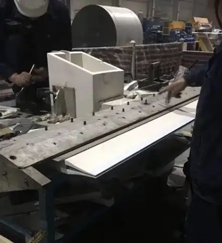
Step 4: Surface Treatment
Coat tip lips with Boron Nitride (BN) for smooth, non-wetting surface. This reduces adhesion and enhances metal flow.
How Can Ceramic Casting Tips Help Reduce Turbulence and Oxide Inclusions?
Laminar flow is critical to reduce oxide inclusions. Field trials show:
| Pour Rate (kg/s) | Inclusion Rate w/ Ceramic Tip (%) | w/o Ceramic Tip (%) |
|---|---|---|
| 5 | 0.10 | 0.15 |
| 10 | 0.18 | 0.25 |
| 20 | 0.32 | 0.40 |
Source: North American industrial trials, confirming improved metal cleanliness.
How Do You Maintain and Optimize the Lifespan of Ceramic Casting Tips?
Regular inspection and cleaning are crucial. For high-volume or fast pours, integrating the tip system with a reliable flow control system ensures consistent metal distribution. Additionally, using proper refining flux or flow equipment can extend tip life and improve overall casting yield.
- Preheat slowly to avoid cracking
- Clean regularly to remove solidified aluminum
- Inspect after every 50–100 pours
Example: A European foundry extended tip life from 40 to 120 pours through careful preheating and inspection routines.
What Are the Limitations of Ceramic Casting Tips That You Should Be Aware Of?
- Ceramic is brittle; handle carefully
- Slightly higher initial cost than steel
- Some automated systems may require reinforced designs
How Can You Optimize Ceramic Tip Usage Over Time for Maximum Efficiency?
| Diameter | Average Life (pours) | Observed Defects | Notes |
|---|---|---|---|
| 25 mm | 90 | 1.5% | Small molds, low-speed pours |
| 35 mm | 100 | 1.2% | Balanced flow & durability |
| 50 mm | 80 | 2% | High-volume, fast pours |
Based on operational logs and industry best practices.
AdTech workers coating ceramic fiber caster tips with Boron Nitride for smooth aluminum flow
If your project requires the use of Ceramic fiber caster, you can contact us for a free quote.
FAQ
1. What is a ceramic casting tip and why is it important?
A ceramic casting tip is a refractory nozzle installed at the end of the pouring system to guide molten aluminum into molds. It improves metal flow, reduces turbulence, and minimizes defects like porosity and oxide inclusions.
2. How does a ceramic tip affect aluminum melt quality?
A well-maintained ceramic tip ensures laminar flow, prevents splashing, and reduces trapped air or oxide inclusions. Combining it with a flow control system and degassing equipment further enhances metal cleanliness.
3. What materials are ceramic casting tips made from?
Common materials include alumina (Al₂O₃), silica (SiO₂), and zirconia (ZrO₂), each offering unique advantages in thermal stability, wear resistance, and chemical resistance depending on alloy type and casting conditions.
4. How do I choose the right tip size for my casting process?
Tip diameter should match your casting volume and alloy viscosity. Oversized tips can cause splashing, while undersized tips may slow mold filling. Trial pours with thermocouples help determine optimal dimensions.
5. What is the role of spacers and hard/soft ears in a caster tip system?
Spacers maintain a uniform gap between the tip and headbox, ensuring proper metal distribution. Hard or soft ears absorb thermal stress and vibrations, stabilizing flow during high-speed or high-volume casting.
6. How should I install and preheat a ceramic casting tip?
Clean the steel holder, preheat tips gradually (200°C → 260°C for several hours), and apply a thin refractory mastic. Coating the tip lips with Boron Nitride (BN) ensures smooth metal release and prevents adhesion.
7. How often should I inspect and maintain ceramic casting tips?
Regular inspection after every 50–100 pours is recommended. Clean tips to remove solidified aluminum, check for surface damage, and replace worn tips to maintain consistent flow and product quality.
8. Can ceramic tips be customized for my production line?
Yes, AdTech offers customized caster tips and associated components like spacers and flow accessories to match specific headbox designs and casting requirements.
9. What common defects are related to poor ceramic tip performance?
Typical defects include porosity, cold shuts, oxide inclusions, streaks, uneven gauge, and edge cracks. These often result from tip deformation, surface erosion, or improper preheating.
10. How can I extend the lifespan of a ceramic casting tip?
Proper preheating, correct installation, using appropriate coatings (BN), regular cleaning, and integrating flow control systems or refining flux can extend tip life and improve casting consistency.