What Role Does the Aluminum Silicate Caster Tip Play in Continuous Casting?
Aluminum and aluminum alloys combine low density, high strength, reliable processing characteristics, and strong welding performance. These properties have made them essential across industrial manufacturing — from automotive body structures and aerospace components to construction cladding and consumer packaging. The Aluminum Association maintains comprehensive data on alloy grades and their mechanical performance across these sectors.
Continuous casting and rolling (CC&R) is currently among the most efficient methods for producing aluminum strip and slab. Compared with traditional ingot-based casting routes, CC&R delivers significantly higher metal yield, better internal slab quality, and measurable energy savings per ton of output. For high-volume rolling mills, it’s become the standard production method.
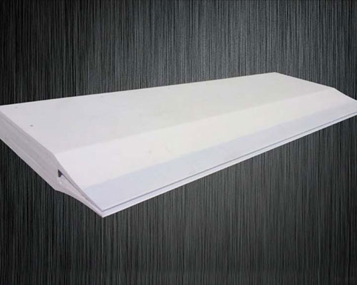
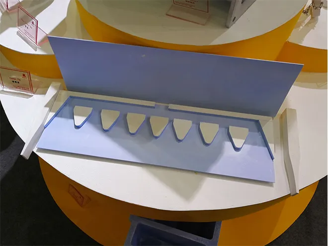
The aluminum silicate caster tip sits at the most critical position in this process. It is the component responsible for distributing molten aluminum evenly from the tundish or tip box into the gap between the casting rolls. Despite its relatively simple appearance — a flat ceramic nozzle with internal channels — it directly governs flow uniformity, temperature distribution across the strip width, and ultimately the metallurgical quality of every meter of strip produced.
Because the caster tip operates in continuous contact with aluminum melt at 680–730°C, it degrades over time through a combination of chemical reaction, thermal cycling, and erosive wear. It is a consumable part by definition. When it blocks — and on many production lines, this happens more often than it should — the entire casting line stops. Cleaning or replacing a blocked tip typically costs 3–5 hours of downtime, not counting the downstream scheduling impact.
Understanding what causes blockage, how to select the right tip material, and how to manage tip life through proper installation and monitoring practices are all directly tied to production efficiency and strip quality. That is the subject of this guide.
Why Does the Caster Tip Block? Detailed Failure Mechanism
Caster tip blockage is the single most disruptive operational issue on a continuous casting line. To address it effectively, the underlying chemistry and physics need to be understood clearly — not in abstract terms, but in the specific sequence of events that occurs inside the nozzle channel during a production run.
When molten aluminum first enters a new caster tip, the channel walls are smooth and the flow velocity is at its highest. At this stage, the aluminum melt reacts with the silicate-based nozzle material at the surface, producing Al₂O₃ (alumina) and free elemental silicon. These reaction products are continuously washed away by the high-velocity melt flow, and the alloy formed by Al₂O₃, silicon, and aluminum enters the melt stream with minimal accumulation on the channel walls.
The problem develops gradually. As hours of production accumulate, two processes work in parallel:
Surface degradation. Reaction products that are not fully removed begin to accumulate on the inner wall surface. This roughens the channel. A rougher surface reduces local flow velocity near the wall. Reduced flow velocity means less scouring energy available to remove the next layer of deposits. The cycle feeds itself — each layer of deposits makes the next layer more likely to stick.
Subsurface penetration. The nozzle material is inherently porous. Molten aluminum doesn’t just react with the surface — it penetrates into the body of the tip through interconnected pore networks, reacting with the material internally. When these interior reaction products are later pulled out by the flow, they leave pits and craters on the channel surface. These pits act as nucleation sites where further slag adhesion occurs preferentially. Research published in the Journal of the European Ceramic Society has documented this subsurface penetration mechanism in detail for alumina-silicate refractories.
There is also a thermal component. The molten aluminum in direct contact with the inner wall of the caster tip is cooler than the bulk melt due to heat loss through the ceramic body. This local temperature reduction increases the viscosity of the melt near the wall, further slowing its velocity and reducing its ability to scour reaction products from the surface.
These three mechanisms — surface reaction accumulation, subsurface material degradation, and thermal viscosity effects — compound over the duration of a casting run. The channel narrows progressively. Flow rate drops. Strip quality begins to deteriorate. Eventually, the channel blocks entirely and the line must be stopped.
This is why porosity is the single most important material property when evaluating caster tip quality. A tip with 40% porosity offers far more pathways for melt penetration and internal degradation than one manufactured to 20% porosity. The difference in service life is not marginal — it is typically a factor of 2x or more under equivalent operating conditions.
How Does Aluminum Silicate Compare to Other Caster Tip Materials?
Several material systems are used for caster tips across the global aluminum casting industry. The choice depends on alloy grade, casting temperature, target service life, and budget constraints. The following table summarizes the key properties.
Table 1: Material Property Comparison — Caster Tip Options
| Property | Standard Aluminum Silicate | High-Density Aluminum Silicate | Fiber-Reinforced Composite | BN-Coated Ceramic |
|---|---|---|---|---|
| Maximum Service Temperature (°C) | 750 | 800 | 820 | 850 |
| Open Porosity (%) | 35–45 | 18–25 | 12–18 | 8–12 |
| Thermal Conductivity (W/m·K) | 0.18–0.22 | 0.14–0.18 | 0.12–0.15 | 0.10–0.13 |
| Flexural Strength (MPa) | 1.2–1.8 | 2.0–2.8 | 3.2–4.1 | 4.5–5.5 |
| Typical Service Life (hours) | 48–96 | 96–168 | 120–200 | 150–250 |
| Resistance to Al Melt Attack | Moderate | Good | Very Good | Excellent |
Property ranges reflect published refractory material data and AdTech internal testing across multiple alloy grades. Actual performance depends on casting speed, alloy chemistry, and melt cleanliness — these values should be used for comparative evaluation, not as absolute guarantees.
For the majority of aluminum rolling mills producing 1xxx, 3xxx, and 8xxx series alloys, high-density aluminum silicate represents the best balance between cost and performance. BN-coated tips offer superior chemical resistance, but at 3–5x the unit cost they are typically reserved for specialty applications — narrow-tolerance aerospace strip, for example, where the cost of a single quality defect far exceeds the tip price difference.
What Specifications Matter Most When Selecting a Caster Tip?
Procurement decisions for caster tips too often focus primarily on unit price and delivery time. From a process engineering perspective, the specifications that actually drive tip performance — and therefore total cost of ownership — are material composition, density, dimensional tolerance, and surface finish.
Table 2: Critical Specification Parameters for Aluminum Silicate Caster Tips
| Parameter | Minimum Acceptable | Recommended Range | Why It Matters |
|---|---|---|---|
| Al₂O₃ Content (%) | 45 | 50–55 | Higher alumina = better resistance to melt reaction |
| SiO₂ Content (%) | Balance | 42–47 | Controls reaction kinetics with aluminum |
| Bulk Density (g/cm³) | 0.38 | 0.48–0.55 | Directly determines porosity and melt penetration resistance |
| Channel Dimensional Tolerance (mm) | ±0.8 | ±0.3 | Governs flow distribution uniformity across strip width |
| Inner Surface Roughness Ra (μm) | ≤3.5 | ≤2.0 | Lower roughness delays onset of slag adhesion |
| Residual Moisture (%) | ≤1.5 | ≤0.8 | Excess moisture causes cracking during preheat |
These specifications are aligned with GB/T 3003 and ISO 2245 standards for refractory fiber products. Alloys with higher Mg content (5xxx series) may require tighter compositional controls due to increased chemical aggressiveness of the melt.
One point that deserves emphasis: dimensional tolerance has a direct, measurable impact on strip quality that is often underestimated. A caster tip with ±0.8 mm channel width variation will produce detectable thickness variation across the strip width. On a 1500 mm wide casting line, this can result in 0.02–0.04 mm strip thickness inconsistency — enough to cause problems in downstream cold rolling or to trigger customer quality claims on precision gauge products. Tightening the tip dimensional tolerance to ±0.3 mm is one of the lowest-cost improvements a mill can make to its strip quality consistency.
How Does Casting Process Design Interact with Caster Tip Performance?
The caster tip does not operate in isolation. Its performance is influenced by — and in turn influences — every upstream and downstream element of the continuous casting process. Understanding these interactions helps explain why the same tip can deliver very different service lives at different facilities.
Melt cleanliness is the most significant upstream factor. Aluminum melt that has been properly treated through degassing and ceramic foam filtration contains significantly fewer oxide inclusions and dissolved hydrogen. Fewer inclusions in the melt means fewer particles available to deposit on the caster tip channel walls, which extends tip life and reduces the rate of channel narrowing. Mills that invest in upstream melt treatment consistently report 30–50% longer tip service life compared with facilities running equivalent tip materials without adequate filtration.
Casting temperature has a dual effect. Higher melt temperatures increase the rate of chemical reaction between the aluminum and the tip material, accelerating surface degradation. However, lower melt temperatures increase melt viscosity, reducing flow velocity and scouring capability. The optimal casting temperature for tip longevity typically falls within a narrower window than the acceptable range for metallurgical quality — usually 695–715°C for 1xxx series alloys.
Line speed affects tip life primarily through its influence on flow velocity inside the channel. Higher casting speeds mean higher flow velocities, which provides better scouring of reaction products but also increases erosive wear. There is a balance point, and it varies by tip material grade and channel geometry.
The International Aluminium Institute publishes process benchmark data that can be useful for comparing your facility’s operating parameters against industry norms.
What Are the Most Frequent Mistakes in Caster Tip Installation?
A well-manufactured tip can still fail prematurely if installation practices are poor. Based on AdTech’s technical service records covering installations in over 40 countries, the following errors account for the majority of avoidable early-life failures.
Table 3: Common Installation Errors and Their Impact
| Error | Typical Root Cause | Consequence | Prevention |
|---|---|---|---|
| Preheat temperature too low | Time pressure during changeover | Thermal shock cracking within first 4–8 hours | Follow preheat SOP: ramp to 550°C at 80°C/hr |
| Tip misalignment in mounting frame | Worn or loose fixturing hardware | Asymmetric flow, strip edge defects | Inspect and calibrate mounting hardware at each changeover |
| Channel contamination before install | Bare-hand handling, dust, no protective packaging | Premature slag nucleation on contaminated surfaces | Handle with clean gloves, inspect channel under light before install |
| Flux residue on tip seating surface | Incomplete launder cleaning between runs | Chemical attack on tip exterior, accelerated degradation | Flush and inspect launder system before each tip installation |
| Storage in uncontrolled humidity | No warehouse climate management | Moisture absorption > 1.5%, cracking at preheat | Store below 60% relative humidity in sealed packaging |
Error frequency data from AdTech technical service records, 2019–2024. Preheat-related failures represented approximately 34% of all early-life tip failures at facilities without formal written installation procedures.
The preheat issue is worth expanding on. Many operators preheat to only 300–400°C, believing this is sufficient. It is not. Aluminum silicate is a ceramic material with relatively low thermal shock resistance. The temperature gradient when 700°C melt first contacts a 350°C tip is severe enough to initiate microcracking in the channel walls — cracking that is invisible externally but creates exactly the kind of rough, porous surface that accelerates slag adhesion and subsurface penetration. Preheating to 550°C with a controlled ramp rate reduces this thermal gradient to a level the material can tolerate without damage.
AdTech Real Case: Production Line Transformation at a Turkish Rolling Mill
In 2024, AdTech was contacted by a mid-capacity aluminum rolling mill located in Konya, Turkey. The facility operated a twin-roll continuous casting line primarily producing 1xxx and 3xxx series strip for the domestic roofing and packaging market. Nominal annual capacity was 18,000 tons, but actual output had stalled at approximately 13,500 tons — a 25% shortfall driven almost entirely by casting line availability issues.
The problem was straightforward: caster tips were lasting an average of 52 hours before requiring replacement due to blockage or unacceptable flow degradation. Each changeover required 3–4 hours of line downtime. At the changeover frequency they were experiencing — roughly 7–8 per month — this translated to 28–36 hours of lost production time monthly. Additionally, strip quality was deteriorating measurably in the final 15–20 hours of each tip’s service life, with surface defects and edge cracking increasing the facility’s scrap rate to 6.8% — well above the 3–4% industry benchmark.
The diagnosis began with a site visit by AdTech’s technical team. Used tips were sectioned and examined. The channel wall surfaces showed heavy Al₂O₃ deposition, deep pitting from subsurface reaction product pullout, and significant melt penetration into the tip body. The tips the facility had been sourcing from a regional supplier were standard-grade aluminum silicate with measured open porosity of 38–42%.
Two additional issues were identified during the visit. First, the preheat protocol was inadequate — tips were being heated to only 350°C before installation. Second, there was no structured tracking of tip performance over each service period, meaning the operations team had no data-driven basis for scheduling replacements and was simply running each tip until it failed.
The implementation had three components:
- Material upgrade. The facility switched to AdTech high-density aluminum silicate caster tips with bulk density of 0.50–0.54 g/cm³ and channel surface roughness Ra ≤ 1.8 μm. Initial order: 48 units, covering approximately six months of projected production.
- Installation procedure revision. AdTech’s on-site technical team trained the facility’s casting crew on a revised preheat protocol — 550°C target temperature, 80°C/hr controlled ramp rate, minimum 2-hour hold at target temperature before installation. This single change eliminated the thermal shock microcracking that had been reducing tip life from the first hour of each run.
- Performance monitoring. A simple log system was introduced, tracking tip installation time, flow characteristics at 12-hour intervals, and tip condition at removal. This gave the plant its first systematic view of how tips were actually degrading over their service life.
Table 4: Measured Results — Before and After AdTech Implementation
| Performance Metric | Before (2020) | After (2021–2022) | Change |
|---|---|---|---|
| Average Tip Service Life | 52 hours | 118 hours | +127% |
| Monthly Changeover Downtime | 28–36 hours | 12–16 hours | -55% |
| Strip Scrap Rate | 6.8% | 3.1% | -54% |
| Actual Annual Output | 13,500 tons | 17,200 tons | +27% |
| Tip Cost per Ton of Output (indexed) | 1.00 | 0.41 | -59% |
Results reflect this specific facility’s operating conditions, alloy mix, and production schedule. Performance at other installations will vary depending on line configuration, alloy chemistry, and casting parameters. Data published with customer authorization.
The output increase from 13,500 to 17,200 tons was achieved without any capital equipment investment — no new casting rolls, no furnace upgrades, no additional staffing. The entire gain came from reduced downtime and lower scrap rates.
Beginning in Q1 2022, the facility expanded its procurement relationship with AdTech to include ceramic foam filters and launder system components . By consolidating their casting consumables supply through a single technical partner, they gained both supply chain simplicity and cross-component compatibility — the filter specifications, launder coatings, and tip materials were all engineered to work together under the same process conditions.
As of 2025, the facility is evaluating AdTech’s online degassing equipment for a planned line expansion. The relationship has evolved from a one-time tip purchase into an ongoing technical partnership.
How Should Caster Tip Replacement Be Scheduled?
The two approaches to tip replacement — run-to-failure and scheduled replacement — produce very different operational outcomes.
Run-to-failure means using each tip until it either blocks or produces unacceptable strip quality. This approach maximizes the service hours extracted from each individual tip, but it comes with significant hidden costs: unpredictable downtime scheduling, elevated scrap rates in the final hours of tip life, and the risk of a mid-shift blockage that disrupts downstream production planning.
Scheduled replacement means establishing a fixed replacement interval based on observed tip performance data, and changing the tip at that interval regardless of apparent condition. This approach sacrifices some usable tip life in exchange for predictable downtime, consistent strip quality, and the ability to schedule changeovers during planned maintenance windows.
For most operations, the scheduled approach produces better total cost outcomes. The key is setting the interval correctly — which requires the kind of performance monitoring data described in the Turkish case study above. Without data, any replacement interval is just a guess.
Practical indicators that a tip is approaching end of useful life include:
- Rising metallostatic head in the tip box — this indicates the channel is narrowing and flow resistance is increasing.
- Deterioration in strip edge quality — edge flow distribution is typically the first area affected as tip geometry degrades.
- Increase in strip surface defect frequency — particularly oxide-related surface inclusions that trace back to dislodged reaction products from the tip channel.
For lines casting 5xxx series alloys, which contain magnesium that is significantly more reactive with silicate-based ceramics, tip replacement intervals should be set 25–35% shorter than for equivalent 1xxx series production runs. The higher reactivity accelerates all three degradation mechanisms described earlier.
What Makes AdTech Aluminum Silicate Caster Tips Different from Commodity Alternatives?
AdTech manufactures its aluminum silicate caster tips from controlled-purity raw materials processed through a proprietary forming and sintering sequence designed to minimize open porosity while maintaining the thermal properties required for continuous casting service.
The measurable differences are:
- Bulk density of 0.48–0.55 g/cm³ — compared with 0.35–0.42 g/cm³ typical of standard-grade alternatives. This density range corresponds to open porosity below 25%, which is the threshold at which subsurface melt penetration rates drop substantially.
- Channel surface finish Ra ≤ 2.0 μm standard, ≤ 1.5 μm available on request. Smoother channel walls delay the onset of slag adhesion and extend the period during which flow velocity is sufficient to maintain self-cleaning action.
- Dimensional tolerance ±0.3 mm standard. This is tighter than many competitors offer and directly impacts strip thickness uniformity.
- Custom geometries for line widths from 400 mm to 2,100 mm. AdTech’s engineering team works directly with customers to optimize channel depth, taper angle, and exit slot geometry for specific alloy grades and casting speeds.
Beyond the tip itself, AdTech supplies a complete range of continuous casting consumables — ceramic foam filters in 20 through 80 PPI grades, degassing systems, launder systems, and flux products. Sourcing these components from a single manufacturer ensures material compatibility across the casting system and simplifies technical support.
How Does Batch-to-Batch Consistency Affect Total Cost of Ownership?
This is a factor that procurement teams frequently overlook. A caster tip supplier quoting 10% lower unit price is not necessarily offering lower total cost — not if their batch-to-batch consistency is poor.
Variable tip quality means variable service life. Variable service life means the production team cannot reliably schedule changeovers, cannot predict downtime, and cannot maintain consistent strip quality across production campaigns. The operational cost of this variability — in scrap, in unplanned downtime, in downstream scheduling disruption — almost always exceeds the unit price savings that motivated the supplier switch.
The relevant questions to ask a prospective tip supplier are not “what is your price?” but rather:
- What is the standard deviation of bulk density within a production batch?
- What is the batch-to-batch variation in measured open porosity?
- How do you verify dimensional conformance — 100% measurement or statistical sampling?
- What raw material incoming inspection do you perform, and how do you trace material to finished product?
If a supplier cannot answer these questions with specific numbers, their process control is likely inadequate for a demanding continuous casting application.
Caster tip performance is not a mystery, and it is not a matter of luck. It is determined by material science, manufacturing process control, installation practice, and operational monitoring — all of which are within the control of the people running the casting line. The facilities that treat their caster tips as precision-engineered process components rather than disposable commodities consistently achieve better uptime, lower scrap, and more predictable production outcomes.
FAQ
1. What is an aluminum silicate caster tip?
An aluminum silicate caster tip is a ceramic component used in aluminum continuous casting to guide molten aluminum into the casting rolls evenly and safely.
2. Why is the aluminum silicate caster tip important?
It directly affects melt flow, strip thickness, surface quality, and casting stability. A poor tip can lead to blockage, downtime, and scrap.
3. Why does a caster tip get blocked?
Blockage usually happens when alumina, slag, and other inclusions build up inside the tip channel during casting.
4. How long does an aluminum silicate caster tip last?
Service life depends on alloy grade, casting temperature, and melt cleanliness, but many plants see anywhere from 50 to 120 hours.
5. What causes early caster tip failure?
Common causes include high porosity, poor preheating, rough inner surfaces, melt contamination, and incorrect installation.
6. How can I extend caster tip life?
Use clean molten aluminum, follow the correct preheating procedure, keep the launder system clean, and choose a high-density caster tip.
7. Is aluminum silicate better than standard ceramic caster tips?
For many rolling mills, high-density aluminum silicate offers a good balance of cost, thermal insulation, and resistance to aluminum melt attack.
8. Can caster tip quality affect strip defects?
Yes. Uneven flow from a worn or poorly made tip can cause edge cracks, thickness variation, and surface defects.
9. How do I choose the right caster tip supplier?
Look at density, porosity, dimensional tolerance, surface finish, and whether the supplier can match the tip to your casting line and alloy.
10. Does AdTech supply other casting consumables besides caster tips?
Yes. AdTech also supplies ceramic foam filters, launder systems, degassing equipment, and other aluminum casting materials for continuous casting lines.