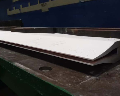
In the aluminum alloy casting and rolling production, the casting tip and nozzle use is a key part of conveying aluminum liquid. The caster tip structure will directly affect whether the melt can enter the casting-rolling zone from the nozzle cavity uniformly and stably, and then affect the quality of the plate. The structural design of the castertip has received extensive attention.
After the melt flows out of the nozzle, there is a self-phase equilibrium flow process. The area with high melt velocity will flow to the area with low velocity, and the area with high melt temperature will transfer heat to the area with low temperature. When the velocity and temperature of the melt at the exit of the casting nozzle fluctuate within a certain range, it will not have a great impact on the quality of the plate. However, the melt must be cooled, solidified, and rolled in a very short time after flowing out of the casting nozzle. The self-equilibrium flow cannot be fully carried out, and the excessive fluctuation range of speed and temperature will inevitably affect the quality of the plate.
When the stoppers at both ends of the nozzle entrance are inclined, the melt is prone to vortex in the nozzle cavity, and bubbles are often formed at the vortex, which causes loose streaks at the corresponding positions of the cast-rolled plate. The presence of eddy currents can also easily lead to instability of the melt flow at the edge of the casting nozzle, resulting in inconsistent edge reduction during casting and rolling, resulting in cracking of the cast-rolled sheet.
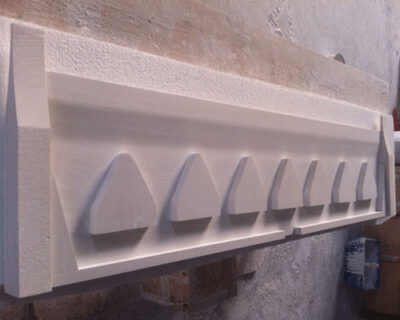
Due to the poor melt fluidity of aluminum alloy plate during casting and rolling production, it is easy to cause insufficient flow at the edge, and the nozzle structure needs to be adjusted to make the internal melt distribution reasonable. The following two adjustment schemes are often used in production:
1) Set the front stop of the nozzle to a certain inclination angle to make the melt easy to flow to the edge, and at the same time set a shunt block in the middle to reduce the intermediate speed.
2) Increase the distance between the shunt block and the stopper, and adjust the distance between the shunt block and the shunt block to make the flow distribution in the cavity reasonable.