There is a moment every casting engineer has experienced at least once: you pull a part out of the mold, it looks fine on the outside, and then it fails inspection. Porosity. Oxide stringers. Inclusions that should never have made it past the gating system. You trace it back, and nine times out of ten, the filtration step is where things went wrong—either the filter was wrong for the application, or it was not as good as the spec sheet suggested.
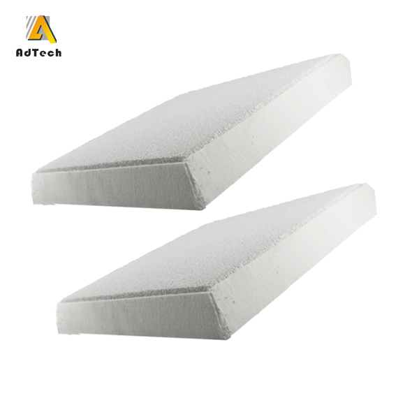
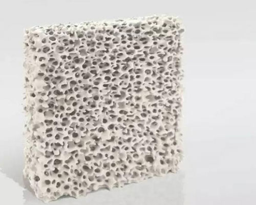
Ceramic foam filters for casting are one of those products that look deceptively simple. A porous ceramic block—how complicated can it be? The answer, once you have spent any real time on a casting floor, is: more complicated than you think. The difference between a filter that works and one that merely looks like it works can mean the difference between a 1.5% reject rate and a 5% reject rate. At production volumes, that gap is not an accounting footnote—it is a serious operational problem.
This page covers what ceramic foam filters for casting actually do, how they are made, how to choose the right one, what the common failure modes look like in practice, and why the manufacturer you source from matters as much as the specification itself.
What Do Ceramic Foam Filters Actually Do in a Casting System?
At the most basic level, a ceramic foam filter removes non-metallic inclusions from molten metal before it enters the mold cavity. But that description undersells what is actually happening.
Molten aluminum, iron, and copper alloys carry a surprising amount of contamination: oxide films that form during melting and handling, refractory particles picked up from furnace linings and ladles, intermetallic compounds that precipitate during cooling, and entrained gas bubbles that attach themselves to solid particles. None of these belong in your finished casting. All of them affect mechanical properties—fatigue strength, elongation, surface finish, and machinability.
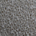
A ceramic foam filter works through two distinct mechanisms. The first is mechanical interception: particles larger than the pore openings are physically blocked. The second—and this is the one that gets underestimated—is adsorption and surface capture. As metal flows through the tortuous path of the foam structure, fine particles that are smaller than the pore size collide with cell walls and stick. This is why a 30 PPI filter captures inclusions well below 30 PPI in effective size. The filter is not just a sieve; it is an active purification surface.
Over the course of a cast, captured inclusions build up on the upstream face of the filter, forming what is known as the filter cake. This layer progressively improves filtration efficiency—it is essentially a secondary filter that develops in real time. Understanding this mechanism matters because it explains why flow rate typically decreases slightly as a cast progresses, and why this is actually a sign the filter is working correctly rather than a problem to be worried about.
Why Are Ceramic Foam Filters for Casting Better Than Other Filtration Methods?
Foundries have used various filtration approaches over the years—strainer cores, woven fiberglass mesh, bonded particle filters. Each has its place, but ceramic foam filters have become the dominant technology for most metal casting applications for a few concrete reasons:
Tortuous flow path: Unlike a strainer or mesh, which offers a relatively direct path for metal to flow through, a ceramic foam filter forces metal to navigate a three-dimensional network of interconnected pores. This dramatically increases contact time between the metal and the filter surface, which is what drives the adsorption mechanism.
High open porosity: Quality ceramic foam filters for casting maintain 80–90% open porosity. This means the filter offers genuine filtration without creating excessive flow restriction that would cause turbulence or cold shuts.
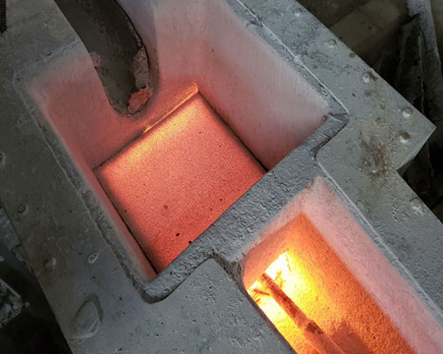
Thermal stability: A ceramic foam filter placed in a properly designed filter seat can withstand the full duration of a cast at metal temperatures well above 700°C for aluminum or 1400°C for iron, without degrading or contributing contaminants of its own.
One-time use simplicity: For most applications, particularly in aluminum semi-continuous casting, the filter is replaced after every cast. There is no cleaning cycle, no regeneration process, no uncertainty about whether last cast’s inclusions are still in the filter.
How Are Ceramic Foam Filters for Casting Actually Made?
This is worth understanding, because the manufacturing process directly determines filter performance—and it explains why two filters with identical spec sheets can behave completely differently on the production floor.
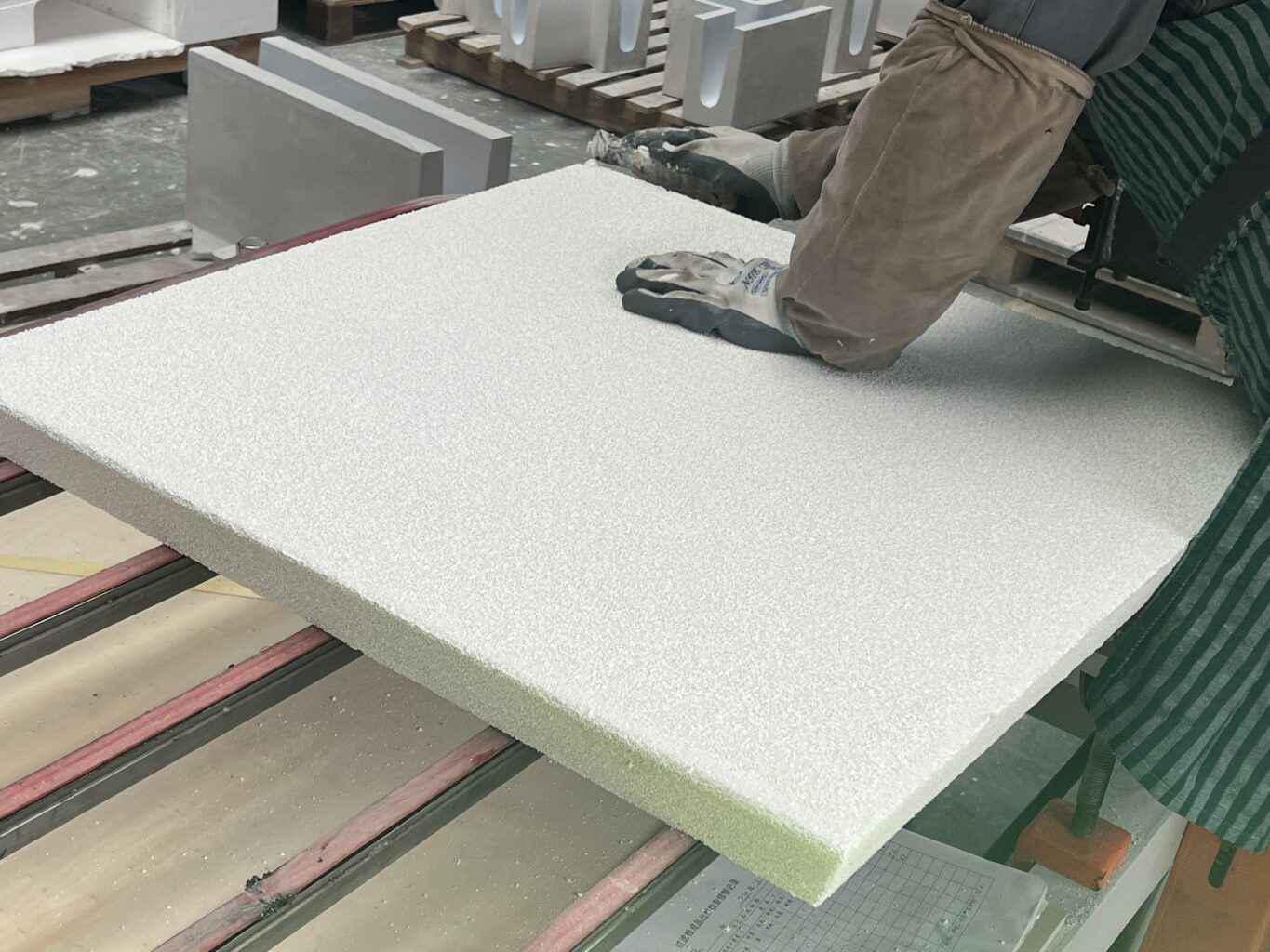
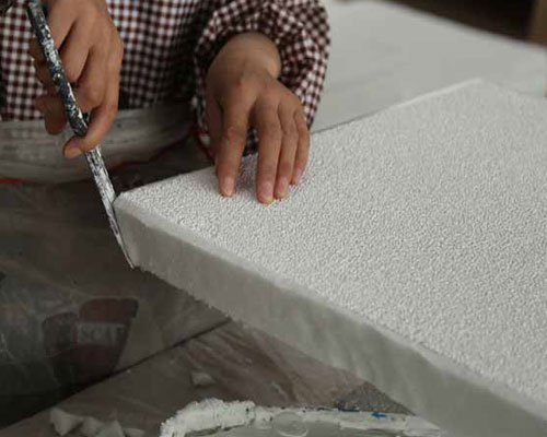
The conventional production route—and still the most widely used—is the foam replication method. A polyurethane foam with interconnected open pores serves as a sacrificial template. This foam is immersed in a ceramic slurry, typically alumina, silicon carbide, or zirconia-based, formulated with specific thixotropic properties so it coats the foam skeleton evenly without blocking the pore openings. The excess slurry is then squeezed out through a rolling process to ensure uniform coating thickness. After drying and solidification, the coated foam goes into a high-temperature kiln: the organic template burns away completely, and the ceramic sinters into a rigid, self-supporting three-dimensional network that mirrors the original foam geometry.
Every step matters. Slurry viscosity determines coating uniformity. The rolling pressure determines whether cells are open or blinded. The sintering profile determines whether the final ceramic has the density and bond strength to survive thermal shock during preheat. A manufacturer who has these parameters dialed in produces a consistently performing filter. One who does not will produce filters that look identical but behave differently from batch to batch.
Beyond the standard foam replication route, researchers and manufacturers have explored several other preparation methods that are worth knowing about—particularly as next-generation filter materials continue to develop:
Freeze-drying is one of the more interesting approaches. The process—vacuum freeze-drying, originally developed in the early 19th century—has been adapted for ceramic production by freezing a ceramic slurry or sol at low temperatures, then sublimating the ice directly to vapor under vacuum. The result is porous ceramics with highly oriented, interconnected pore structures and porosity exceeding 90 vol% in some formulations. The directionality of ice crystal growth can be controlled to produce aligned pore channels, which is useful for applications where consistent flow behavior is critical.
Template methods offer the most precise control over pore geometry. The polymer template approach, for instance, uses core-shell structures—polymer core, ceramic shell—which are then calcined to remove the polymer and leave behind a controlled porous ceramic network. Researchers have demonstrated this technique with alumina, titania, and zirconia systems at nanoscale pore sizes with tight size distributions. A more unusual variant uses natural wood as the template: the wood is impregnated with ceramic precursors, carbonized, and then converted through reactive melt infiltration or carbothermal reduction. The resulting ceramics retain the wood’s microstructural organization, with porosity ranging from roughly 20 to 80 vol% depending on wood species and preparation route.
Biomimetic synthesis takes a different approach entirely—using surfactant self-assembly to create templated pore structures. Surfactants that form vesicles or liquid crystal phases in water can direct the condensation of ceramic precursors around their structures, yielding layered or spherical porous ceramics with very fine, controlled pore sizes in the sub-millimeter range.
Mechanical foaming is simpler in concept: surfactants and foaming agents are added to a ceramic sol or suspension, and mechanical stirring generates a foam that is then dried and fired. Work from the early 1990s demonstrated this approach for porous silica, achieving uniform pore structures with compressive strengths around 1.4 MPa in some formulations. The process is relatively straightforward to scale, which makes it attractive for production environments where the exotic precision of template methods is not required.
For most industrial casting filtration applications, the foam replication route remains dominant because it combines adequate pore control with the kind of production throughput that large foundry supply chains require. The newer methods are more relevant to specialty ceramics and emerging filter generations designed for ultra-fine inclusion capture. AdTech’s production uses optimized foam replication with continuous process monitoring—the established approach, executed with the rigor that distinguishes a consistent product from an inconsistent one.
What Types of Ceramic Foam Filters for Casting Are Available?
Material selection is the first decision, and it is non-negotiable—get it wrong and the filter either fails thermally or chemically reacts with your melt:
| Filter Material | Working Temperature | Best For | Typical PPI Range |
|---|---|---|---|
| Alumina (Al₂O₃) | Up to 1200°C | Aluminum alloys, copper alloys | 10–60 PPI |
| Silicon Carbide (SiC) | Up to 1500°C | Gray iron, ductile iron, malleable iron | 10–40 PPI |
| Zirconia (ZrO₂) | Up to 1700°C | Carbon steel, alloy steel, superalloys | 10–30 PPI |
Material classification and temperature ratings are consistent with guidelines published by the American Foundry Society (AFS) and industry ceramic engineering references. Actual service temperatures depend on specific alloy chemistry and contact time.
AdTech manufactures alumina, silicon carbide, and zirconia ceramic foam filters across the full PPI range, in standard sizes from 12×12 inches to 26×26 inches. Custom dimensions and non-standard chemistries are available with typical lead times of 2–3 weeks. The full product range is listed at AdTech’s product page.
How Do You Choose the Right PPI for Your Application?
PPI—pores per inch—is the specification that confuses buyers most often. Higher PPI means finer filtration and more inclusion capture, but also higher flow resistance and more sensitivity to priming conditions. Lower PPI means easier metal flow but less effective filtration of fine particles.
Here is how to think about it practically:
10–20 PPI: Coarse filtration. Used where metal flow rate is the priority and gross inclusion removal is the goal. Common in large iron castings, ingot casting, and applications where cleanliness requirements are not stringent.
30 PPI: The workhorse of aluminum casting. Balances filtration efficiency with reliable priming behavior across a wide range of alloys and temperatures. A solid default choice for most aluminum semi-continuous casting and gravity die casting applications.
40–50 PPI: Fine filtration for demanding applications. Automotive structural components, aerospace billets, thin-wall precision castings. These filters require careful preheat management and slightly higher metallostatic pressure to prime reliably, but the inclusion capture performance justifies it.
60 PPI: Specialty grade for ultra-clean casting applications. Not commonly stocked; typically produced to order.
One practical note: if you are unsure where to start, run your current process at 30 PPI and commission a PoDFA (Prefil Oxfilm Filtration Analysis) or LiMCA (Liquid Metal Cleanliness Analyzer) test on cast samples. The inclusion population data will tell you whether you need to go finer or whether 30 PPI is already giving you what you need. Making a PPI change based on data rather than intuition is always the right approach.
What Are the Most Common Failure Modes for Ceramic Foam Filters in Casting?
Knowing what can go wrong—and why—is genuinely useful, especially when you are troubleshooting a quality problem and trying to figure out whether the filter is the culprit.
Thermal shock cracking during preheat
The most common failure, and almost always avoidable. When a cold filter is exposed to rapid, high-intensity heating, the thermal gradient between the surface and the core generates stress that fractures the ceramic. Fragments enter the mold. The fix is gradual preheat—lower initial flame intensity, longer ramp time. A filter that consistently cracks during your standard preheat procedure is either underfired during manufacturing or your preheat protocol needs adjustment. Usually both need to be looked at.
Incomplete priming / channeling
Metal breaks through the filter at one or two points while the rest of the filter face stays dry. This happens when the filter is cold, when metallostatic head is insufficient, or when the filter seat geometry does not distribute pressure evenly across the filter face. Channeling dramatically reduces effective filtration area and increases local metal velocity through the open channels—often creating new turbulence-induced oxides rather than removing existing ones.
Erosion and particle shedding
Cell walls in a poorly sintered filter erode progressively under metal flow, releasing ceramic fragments into the melt. This is the failure mode that is hardest to detect because ceramic fragments in a casting are nearly indistinguishable from oxide inclusions in most inspection methods. The giveaway is a step-change in your inclusion counts that correlates with a supplier change or a new production batch.
Edge seal failure
If the filter does not sit properly in its seat—whether due to dimensional inconsistency or poor filter bowl design—metal bypasses the filter entirely around the edges. You get no filtration benefit and a false sense of security. Reliable ceramic foam filter manufacturers hold dimensional tolerances tight enough (typically ±1.5mm) to ensure consistent seating.
What Should a Ceramic Foam Filter Specification Sheet Actually Tell You?
When you are evaluating ceramic foam filters for casting from different suppliers, you will receive spec sheets that all look broadly similar. Here is what the numbers actually mean in practice—and which ones you should push for if they are missing:
| Parameter | What to Look For | Why It Matters |
|---|---|---|
| Open Porosity | 80–90% | Below 80% indicates excessive slurry loading; above 90% suggests insufficient structural strength |
| Compressive Strength (cold) | ≥ 1.0 MPa for alumina grades | Predicts handling durability and resistance to breakage in the filter seat |
| Bulk Density | 0.3–0.6 g/cm³ | Outside this range suggests process inconsistency in slurry application or sintering |
| PPI Tolerance | ±2 PPI specified and measured | Loose PPI control leads to channeling and inconsistent flow behavior |
| Al₂O₃ Content (alumina filters) | ≥ 84% for standard grade | Lower alumina content reduces thermal stability and chemical resistance |
| Thermal Shock Resistance | No cracking after 3+ cycles at 1100°C | Predicts preheat survivability under real production conditions |
Specification benchmarks consistent with ASTM C133 test methods and American Foundry Society filtration guidelines. AdTech provides third-party lab test reports on compressive strength and chemical composition upon request.
If a supplier cannot provide measured data for compressive strength, PPI tolerance, and chemical composition—not just nominal values, but actual batch test data—that is a meaningful gap in their quality documentation.
AdTech Real Case: Rebuilding a Malaysian Automotive Aluminum Foundry’s Filtration Process
A mid-sized aluminum casting facility in Shah Alam, Malaysia—producing suspension components and engine brackets for Japanese automotive OEM supply chains—came to AdTech in early 2024 with a straightforward but frustrating problem: their scrap rate had drifted upward over 18 months, from a historical average of around 2.1% to a current rate sitting stubbornly at 4.3%. Their existing ceramic foam filter supplier had not changed. Their alloy charge composition had not changed. Nothing obvious had changed. But the parts were failing radiographic inspection at a rate that was starting to affect their delivery performance and customer relationship.
Their production setup at the time: a gravity die casting line running A380 aluminum alloy, with 15×15 inch, 30 PPI alumina filters sourced from a regional supplier in Thailand. They were not running any inline degassing—relying entirely on furnace-side flux treatment for hydrogen removal.
AdTech’s technical team reviewed the situation and identified three contributing factors:
First, the existing filters showed significant PPI variation within individual units—some areas of the filter face were running effectively at 25 PPI while others were closer to 38 PPI. This was confirmed by flow testing and cross-section analysis. The inconsistency was causing uneven metal distribution across the filter face and localized channeling.
Second, without inline degassing ahead of the filter, hydrogen levels in the melt were high enough that the filter was essentially being asked to compensate for upstream process deficiencies it was never designed to handle on its own.
Third, the preheat station had no temperature monitoring—operators were judging preheat completion visually, leading to significant cast-to-cast variation in filter temperature at first metal contact.
AdTech proposed a phased solution. In the first phase, we supplied 200 units of 15×15 inch, 30 PPI Ceramic Foam filters and conducted a controlled comparison against the existing supplier’s product on the same casting line. The AdTech filters demonstrated tighter PPI consistency and significantly better priming uniformity, confirmed by flow rate measurements taken at 15-second intervals during the first 60 seconds of each cast.
In the second phase, AdTech recommended the addition of a compact trough-type online degassing unit upstream of the filter station—a product also within AdTech’s range. The combined degassing-plus-filtration approach brought hydrogen levels down to below 0.12 ml/100g Al before metal reached the filter.
Results after 90 days of full implementation: scrap rate dropped from 4.3% to 1.4%—below their historical baseline. Radiographic rejection at the OEM’s incoming inspection facility fell by 68%. The plant’s quality manager noted that several components previously requiring manual rework were now passing first-time inspection consistently.
The Malaysian facility now operates under a quarterly supply agreement with AdTech covering ceramic foam filters, degassing rotors, and flux powders. The relationship started because a filter was not working right—and ended up touching multiple points of their purification process. That is typically how it goes when the supplier actually understands casting rather than just selling into it.
If your project requires the use of Ceramic Foam Filter, you can contact us for a free quote.
How Is Ceramic Foam Filter Technology Developing?
The basic foam replication process has been in use since the late 1970s, but the technology has not stood still. A few directions that are genuinely reshaping what these filters can do:
Surface-modified filters: Standard ceramic foam filters capture inclusions primarily through mechanical means. Next-generation filters incorporate reactive surface coatings—typically flux-based or oxide chemistry modifications—that actively attract and bind fine inclusions through chemical affinity. This is particularly relevant for ultra-fine oxide films below 10 microns that mechanical filtration alone struggles to capture. The freeze-drying and biomimetic synthesis methods mentioned earlier are central to this development—they allow researchers to engineer surface chemistry and pore geometry simultaneously in ways that the conventional foam replication route cannot easily achieve.
Dual-stage filtration systems: Running a coarser filter (10–20 PPI) upstream of a finer filter (40–50 PPI) extends the service life of the fine filter while achieving very low final inclusion counts. The coarse filter handles the bulk of gross inclusions; the fine filter addresses the remainder. AdTech has supplied dual-stage filter assemblies for several high-cleanliness aluminum billet casting lines.
Wood-templated and biomorphic ceramics: An emerging research direction that is starting to find industrial application—using natural wood microstructure as the template produces ceramics with highly organized, anisotropic pore networks that offer uniquely consistent flow behavior. Porosity in these materials can be tuned from roughly 20 to 80 vol% by selecting different wood species and preparation routes.
The global ceramic foam filter market is projected to grow at approximately 5.5% CAGR through 2030, driven by tightening inclusion standards in automotive lightweighting applications and expanding aluminum consumption in electric vehicle structural components.
Why AdTech for Ceramic Foam Filters for Casting?
AdTech is not the largest ceramic foam filter manufacturer in the world. What the company has built over more than two decades is something more useful to most foundries: deep process knowledge, genuine manufacturing control, and a technical support model that actually involves engineers rather than just account managers.
The filters are produced at AdTech’s Jiaozuo, Henan facility under ISO 9001-certified quality systems. Raw materials go through incoming XRF and particle size analysis before production. Slurry viscosity is monitored continuously on the coating line. Kiln temperature profiles are programmed and logged for every batch. Final inspection covers compressive strength, dimensional tolerance, and visual assessment of cell structure uniformity.
None of that is marketing language—it is just what a well-run ceramic production facility does. The reason it is worth stating is that a meaningful number of suppliers in this category do not do all of it, and the difference shows up in your casting quality data even when it is invisible on the spec sheet.
If you are running ceramic foam filters for aluminum casting, iron casting, copper casting, or steel casting and your current results are not where they need to be—or if you simply want to know whether there is a better option— AdTech’s team is worth a conversation. Send them your current filter spec, your alloy, and your quality targets. The response will come from someone who understands what those numbers mean on a casting floor.
1. What is a ceramic foam filter used for in casting?
It removes non-metallic inclusions—oxides, intermetallics, refractory particles—from molten metal before it enters the mold. Think of it as the last line of defense before metal hits the cavity. Without it, those inclusions end up in your finished part, where they show up as porosity, surface defects, or premature fatigue failures in service.
2. Which ceramic foam filter material should I use for aluminum casting?
Alumina (Al₂O₃)-based filters are the standard choice for aluminum alloys. They are chemically compatible with aluminum melts, thermally stable up to around 1200°C, and available in the full PPI range. Silicon carbide and zirconia filters are designed for higher-temperature applications like iron and steel—using them for aluminum is unnecessary and more expensive.
3. What PPI should I use for aluminum die casting versus sand casting?
For gravity die casting and most sand casting applications, 30 PPI is a reliable starting point. If you are casting thin-wall parts or supplying automotive OEMs with strict radiographic inspection requirements, 40 PPI is worth considering. High-pressure die casting typically does not use ceramic foam filters due to the speed and pressure of the process—filtration happens upstream in the furnace instead.
4. Can I reuse a ceramic foam filter after casting?
No—and you should not try. Ceramic foam filters for casting are single-use in semi-continuous and most batch casting applications. After a cast, the filter is saturated with captured inclusions and retained metal. Reusing it introduces all of that contamination into your next cast. The filter cost is small relative to the risk of a contaminated heat.
5. Why is my ceramic foam filter not priming properly?
Three likely culprits: the filter is too cold going into the cast, metallostatic head is insufficient for the PPI selected, or the filter seat geometry is not distributing pressure evenly across the face. Start by checking your preheat—most priming failures trace back to a filter that has not reached temperature uniformly. If priming is consistently slow or uneven, dropping from 40 PPI to 30 PPI will also help while you diagnose the root cause.
6. How do I know if my ceramic foam filter is shedding particles into the melt?
It is not easy to detect visually, which is what makes this failure mode dangerous. The clearest sign is a sudden increase in inclusion counts—confirmed by PoDFA or LiMCA analysis—that correlates with a change in filter supplier or a new production batch. If your X-ray reject rate spikes without any obvious process change, filter erosion should be on your shortlist of suspects.
7. What size ceramic foam filter do I need?
Filter size is determined by your metal flow rate and total pour volume. As a general rule, the filter face area should be large enough that metal velocity through the filter stays below the threshold where erosion and turbulence become concerns—typically under 10 cm/s for aluminum. Your filter supplier should be able to size the filter based on your gating system geometry and pour weight. Standard sizes run from 7×7 inches up to 23×23 inches.
8. What is the difference between ceramic foam filters and bonded particle filters?
Bonded particle filters—sometimes called ceramic filter balls or extruded filters—have a simpler, more regular pore structure than foam filters. They are generally cheaper and easier to prime, but they offer less surface area for inclusion adsorption and a less tortuous flow path. For applications where moderate cleanliness is acceptable, they can work fine. For anything where low inclusion counts are critical, ceramic foam filters consistently outperform them.
9. How should ceramic foam filters be stored before use?
Keep them in original packaging in a dry environment—humidity absorbed into the ceramic converts to steam during preheat and can cause cracking from the inside out. Do not stack filters without separators between them, and inspect edges and corners before installation since that is where shipping damage tends to concentrate. A filter with a hairline crack from storage will fail during preheat, often without obvious warning.
10. How do freeze-drying and template methods differ from standard ceramic foam filter production?
Standard ceramic foam filters are made by the foam replication method—coating a polyurethane foam template with ceramic slurry, then burning out the foam during sintering. Freeze-drying and template methods are more recent techniques that offer tighter control over pore geometry and higher achievable porosity (sometimes exceeding 90 vol%), which makes them relevant for next-generation filter development. For current industrial casting applications, foam replication remains dominant because of its production scalability, but the newer methods are driving where high-performance filtration technology is heading.