1. Technical field:
The utility model relates to a combination device of rigid motion and flexible motion when an electric push rod moves, in particular to an electric push rod flipping device for a launder system cover with high safety and long service life.
2. Utility model patent personnel:
Ren Junjun, Xiong Xuejun, Wang Haibo, Zhang Xiaozhuang, Zhang Haiyou, Luo Hao, Li Pengfei, Yue Yaju
3. Background technology:
At present, in the aluminum water purification industry, the launder system used for passing aluminum water needs to be covered for heat preservation, and some need to be heated by an electric heating cover. The launder cover needs to be in the form of automatic flipping. Source, use the principle of leverage to flip. Since the electric push rod transmission belongs to the rigid transmission form, when there is no debris on the contact surface of the launder and the launder cover, the electric push rod flip cover of the launder cover works normally; There is a gap with the launder system cover, the stroke of the electric push rod should be shortened theoretically, but the stroke of the electric push rod will still transmit power according to the predetermined stroke, and the stroke of the electric push rod will stop when it is in place. The rigid transmission will cause the electric push rod to bend, deform and break, or the worm tooth type inside the electric push rod will be broken due to excessive force, making the electric push rod unable to continue to work, which will have a great impact on production, and after replacing the electric push rod It will also be damaged from time to time; the utility model patent provides a new type of intelligent launder system cover electric push rod flipping device, which is simple to operate, easy to install, and has high safety performance, greatly reducing the replacement cost of electric push rods, and also reducing staff replacement. The labor intensity of the electric push rod improves production efficiency.
4. Contents of the utility model:
The key points of this utility model patent: 1) Adopt a combination device of rigid motion and flexible motion; 2) There are 4 waist-shaped holes on the lower hinge plate to ensure that it can have a certain amount of slippage on the connecting base; 3) There are two tension springs symmetrically on both sides of the lower hinged plate to ensure smooth sliding when the lower hinged plate slides; 4) The tension of the stretched spring is greater than the weight of the launder cover and less than the thrust of the electric push rod; 5) The lower hinged plate is on the connecting base It can slide freely; 6) When the lower hinge plate slides, it is guided by 4 hexagon socket head screws.
The technical problem to be solved by the utility model patent is: to overcome the deficiencies of the prior art and provide a new type of electric push rod flipping device for intelligent launder cover. This new type of intelligent runner cover electric push rod flip device adopts the concept of combining an electric push rod (rigid transmission) and spring buffer device (flexible transmission), which solves the problem of using a spring when the electric push rod stroke is blocked due to various reasons. The buffer device is used to solve the problem of the stroke of the electric push rod. It can greatly reduce the damage rate of the electric push rod and improve the production efficiency of the enterprise. It not only completely eliminates the potential safety hazards when the electric push rod of the launder system cover is turned over but also greatly reduces the production cost. Replacing the electric push rod will cause harm to employees, reduce the work intensity of employees, ensure the safe operation of production, and improve work efficiency and production efficiency.
The technical scheme that the utility model takes for solving the technical problem is:
The new intelligent runner cover electric push rod flip device includes the runner, the runner cover, the connecting base, the hexagon socket head screw, the lower hinge plate, the electric push rod, the tension spring, the swing bolt, the spring fixing seat, the nut, lever mechanism. The new intelligent launder cover electric push rod flip device also includes a power supply, an operation box, etc. The intelligent launder cover electric push rod flip device, when the power is turned on, the button is turned to the flip position, the electric push rod starts to shorten the stroke when it is powered on, and the launder system cover is slowly turned over through the lever mechanism. The hexagonal cylindrical head screws are in close contact (under the action of the spring force). When the electric push rod is at the shortest stroke, the electric push rod completes its movement and stops. At this time, the opening angle of the launder cover is greater than 84°, and the launder can be observed The internal aluminum liquid or the aluminum slag inside the launder is cleaned; when there is no foreign matter on the sealing surface of the launder and the launder cover (the employee has cleaned it up) when the button is turned to the closing position, the electric push rod is energized and starts to extend the stroke movement, through the lever mechanism The launder cover is turned over slowly, and the lower part of the waist-shaped groove on the lower hinge plate is in close contact with the hexagon socket head screw (under the action of the spring force). When the electric push rod reaches the maximum stroke, the electric push rod moves and stops. At this time, the launder system cover and the launder cover are well sealed; when there is a foreign object on the contact surface between the launder and the launder cover (the employee did not notice or did not clean it up), there is a gap between the launder and the launder cover, and the electric push rod extends The stroke should be reduced. When the button is turned to the cover closing position, the electric push rod is energized and starts to extend the stroke movement, and the launder cover is slowly turned over through the lever mechanism. The lower part of the waist groove on the lower hinge plate is in close contact with the hexagon socket head screw ( Under the action of the spring force), the motion of the electric push rod is a rigid transmission, and the stroke of the electric push rod will not be automatically reduced. The electric push rod must reach the maximum stroke before the electric push rod can stop. sundries) can not continue to close the movement, while the electric push rod continues to increase the stroke, when the push force of the moving electric push rod is greater than the tension of the spring, the lower hinge plate is forced to move down along its waist groove to accommodate the electric push rod To achieve the maximum stroke, to reduce the damage to the electric push rod due to excessive force, and to protect the electric push rod to work stably for a long time.
The positive beneficial effects of the utility model are as follows:
1. The utility model patent is simple in structure, reasonable in design, low in cost, easy to implement, and realizes the dual purposes of economy and high efficiency so that economic benefits and labor intensity of employees are both technically guaranteed.
2. Adopting the utility model patent can reduce the labor intensity of employees, greatly reduce the production cost of the enterprise (reduce the cost of replacing the electric push rod), and greatly improve the production efficiency of the enterprise.
5. Description of drawings:
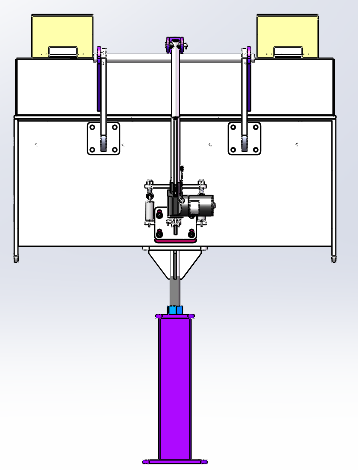
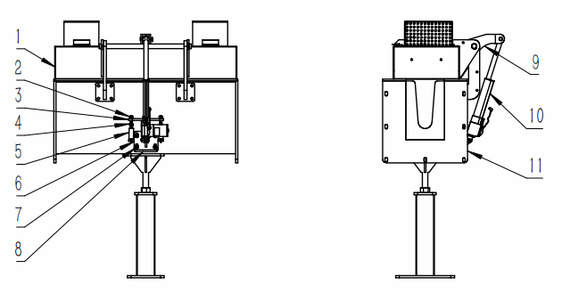
Fig. 1 is the structural representation of the utility model.
6. Specific implementation methods:
Below in conjunction with the accompanying drawing and implementation the utility model is further explained and illustrated:
Assembling of the intelligent runner cover electric push rod flip device: the contact surface of the runner 11 and the runner cover 1 is in good contact, the electric push rod 10 is at the maximum stroke state, the connecting base 8 is welded on the shell of the runner 11, and the lower hinge plate 6 passes through the inner The hexagonal cylindrical head screw 7 is fixed on the connecting base 8, and the lower hinge plate 6 can slide freely on the connecting base 8, and the hexagonal cylindrical head screw 7 plays a guiding role. When installing, the lever mechanism 9 is fixed on the launder cover 1; One end of the electric push rod 10 is hinged on the lever mechanism, and the other end is hinged on the lower hinged plate 6; one end of the tension spring 5 is connected to the shaft at both ends of the lower hinged plate 6, and the other end is connected to the lower part of the swing bolt 4, and through the nut 2 Connected to the spring fixing seat 3, adjust the tension of the tension spring 5 by adjusting the nut 2, the tension spring 5 drives the lower hinge plate 6 to move upward so that the bottom of the waist groove of the lower hinge plate 6 and the hexagon socket head screw 7 Close contact with a certain pre-tightening force, the pre-tightening force is greater than the weight of the launder cover and less than the thrust of the electric push rod 10.
Launder cover 1 flip work: turn on the power, the button is turned to the flip position, the electric push rod 10 is energized and starts to shorten the stroke, and the lever mechanism 9 drives the launder cover 1 to flip slowly. At this time, the lower part of the waist groove on the lower hinge plate 6 is In close contact with the hexagon socket head cap screw 7 (under the action of the tension spring 5), when the electric push rod 10 is in the shortest stroke, the electric push rod 10 completes its movement, stops the movement, and completes the work of flipping the launder cover 1. At this time, the opening angle of the launder cover 1 is greater than 84°, so that the aluminum liquid inside the launder 11 can be observed or the aluminum slag inside the launder system 11 can be cleaned.
The launder cover 1 is normally closed: when there is no foreign matter on the sealing surface between the launder 11 and the launder cover 1 (the employee has cleaned it up), turn on the power, and the button is turned to the cover closing position, and the electric push rod 10 starts to extend the stroke when it is powered on. Through the lever mechanism 9, the runner cover 1 is slowly turned over, and the lower part of the waist-shaped groove on the lower hinge plate 6 is in close contact with the hexagon socket head screw 7 (under the action of the tension spring 5), when the electric push rod 10 is at the maximum stroke, the motion of the electric push rod 10 is completed, stops the movement, and completes the work of closing the launder cover 1. At this time, the launder cover 1 and launder 11 are well sealed, and everything is normal.
Abnormal closing operation of the launder cover 1 (this kind of phenomenon often occurs): When there is a foreign object on the contact surface between the launder 11 and the launder cover 1 (the staff did not notice or did not clean it up), turn on the power, and the button turns to close the cover position, the electric push rod 10 is energized and starts to extend the stroke movement, and the launder cover 1 is slowly turned over through the lever mechanism 9, and the lower part of the waist groove on the lower hinge plate 6 is in close contact with the hexagon socket head screw 7 (in the tension spring 5 under the action of the runner), because there are foreign objects on the contact surface between the runner 11 and the runner cover 1, the contact surface between the runner 11 and the runner cover 1 cannot be sealed well, and there is a gap in the middle. The stroke of the electric push rod 10 should be reduced theoretically, but the electric push rod movement of the rod 10 belongs to the rigid transmission, so the stroke of the electric push rod 10 will not be automatically reduced, the electric push rod 10 must reach the maximum stroke before the electric push rod 10 can stop moving, at this time, the electric push rod 10 pushes the lever mechanism 9 to make the launder cover 1 moves downward, due to foreign matter, the runner cover 1 cannot continue to move downward, and the electric push rod continues to increase the stroke. When the thrust of the moving electric push rod 10 is greater than the tension of the tension spring 5, the lower hinge has forced plate 6 to slide down along its waist-shaped groove to release the unfinished stroke of the electric push rod 10, so as to prevent the electric push rod 10 from reaching the maximum stroke and damage the electric push rod 10 due to excessive thrust generated by the electric push rod 10, thereby protecting the electric push rod 10. The push rod 10 can work stably for a long time.
When the sealing of the contact surface between the launder 11 and the launder cover 1 is not tight, remove the foreign matter between them and close the cover again.