Why Do You Need Ceramic Foam Filters in Aluminum Casting?
Ceramic foam filters exist for one main reason: they clean molten aluminum before it reaches the mold. In practice, that means capturing oxide films, refractory debris, sludge, and other nonmetallic inclusions that can cause porosity, surface defects, hot tearing, and machining rejects. For high-spec markets—like aerospace castings, automotive structural parts, and medium-micron aluminum foil—those defects are simply unacceptable.
A well-chosen filter does more than trap inclusions. It also helps regulate flow, reduce turbulence, and prevent “jetting” that can shear oxides off the launder walls and re-contaminate the melt. That’s why, in many modern cast houses, ceramic foam filters aren’t treated as a commodity item—they’re treated as a controlled process step, with documented pore size, installation geometry, preheat practice, and changeout frequency.
If you’re aiming for consistent PoDFA results, stable casting temperature, and fewer downstream rejects, the right filtration setup is usually the fastest path to measurable improvement.
How to Choose Ceramic Foam Filters Based on Your Casting Process?
What Kind of Casting Line Are You Running?
Your casting process drives the filter selection more than almost anything else. A DC billet caster has different flow rates, thermal demands, and cleanliness targets than a gravity sand casting line or a low-pressure die casting cell.
- DC casting (billets/ingots): You typically need filters that can handle high throughput, stable metal head, and consistent flow into the distribution launder. Pore size and filter area are critical because any channeling can show up as macrosegregation or surface defects on the billet.
- Gravity casting (sand, permanent mold): You often prioritize inclusion removal and flow smoothing. Filter sizing is still important, but the main goal is clean metal into the mold cavity with minimal turbulence.
- Rolling/foil production: Cleanliness at the casting stage cascades into foil quality. Inclusion-related pinholes and surface streaks are common pain points, so filtration becomes part of the core quality plan.
If you’re unsure where to start, a practical move is to review your current defect Pareto chart and trace the most persistent issues back to melt handling. In many plants, that leads straight to the transfer and filtration stage.
How Do You Match Pore Size (PPI) to Inclusion Control?
Pore size, commonly given as PPI (pores per inch), is one of the first specs people look at—but it’s not the only one. Higher PPI generally means finer filtration, but it also means higher pressure drop and greater sensitivity to preheat and flow rate.
| Application | Typical PPI | Primary Goal | Watch-Outs |
|---|---|---|---|
| DC billet casting (6063/6061) | 30–50 PPI | Balanced inclusion removal + stable flow | Avoid over-filtering that causes excessive pressure drop |
| Precision castings (aerospace/automotive) | 40–60 PPI | Maximum inclusion capture | Ensure proper preheat and filter box sealing |
| Rolling/foil stock | 30–50 PPI | Clean metal with stable temperature | Match filter area to throughput to prevent channeling |
| Foundry remelt with heavy inclusions | 20–40 PPI | Robust filtration with lower pressure drop | Combine with degassing for best results |
This table reflects common industry practice in aluminum casting and is aligned with typical AdTech product recommendations. Data is informed by field performance across multiple foundries and supported by internal process audits.
How to Use Ceramic Foam Filters Correctly During Operation?
Choosing the filter is only half the job—how you install and run it determines whether you get the promised results.
- Preheat properly. Ceramic foam filters must be preheated to remove moisture and reduce thermal shock risk. A controlled ramp to around 500–600 °C (or per your filter box design) is usually the right target. If you skip preheat or rush it, you risk filter cracking and melt bypass.
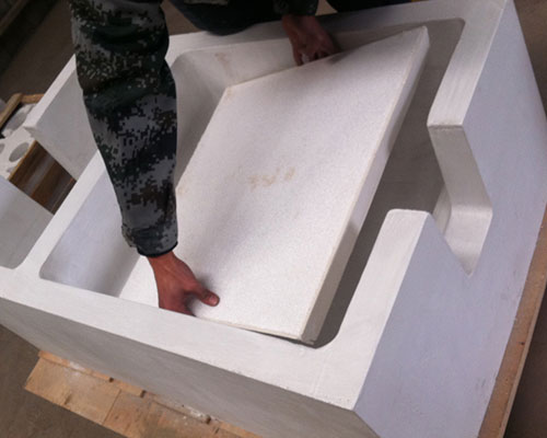
- Seal the filter box. Gaps around the filter create bypass routes for dirty metal. Use correct gasketing and ensure the filter sits squarely in the holder. Bypass is one of the most common hidden causes of “filter didn’t work” outcomes.
- Control metal head and flow rate. Excessive head can fracture the filter or force channeling. Too little head can stall flow and destabilize casting temperature. Your filter box and launder design should keep metal level steady.
- Change filters on a schedule. Waiting until you see a problem often means you’ve already generated scrap. Track campaign length, inclusion trends, and filter pressure/flow behavior. Many plants set changeout based on tonnage or time, then refine it with PoDFA sampling.
These steps are where AdTech’s engineering support can make a real difference. Our team often reviews filter box geometry, gasket design, and preheat practice as part of a complete molten aluminum handling upgrade—especially when paired with our ceramic launder systems.
What Filter Dimensions and Area Should You Specify?
How to Size Filter Area for Your Throughput?
Undersized filter area is a silent killer. It increases pressure drop, accelerates channeling, and can push metal through only part of the filter—defeating the whole point of filtration.
| Throughput (tonnes/hour) | Recommended Filter Area (cm²) | Common Filter Size | Notes |
|---|---|---|---|
| ≤ 2 t/h | 200–400 cm² | 7″ × 7″ or similar | Suitable for smaller foundries and low-pressure lines |
| 2–6 t/h | 400–800 cm² | 9″ × 9″ to 12″ × 12″ | Balance pressure drop and inclusion capture |
| 6–12 t/h | 800–1,500 cm² | 15″ × 15″ or multiple filters | Consider multi-filter filter box design |
| > 12 t/h | 1,500+ cm² or multi-filter | Custom filter box | Engineering review recommended |
Sizing guidance reflects practical field experience and common best practices in aluminum casting operations. Data is derived from process engineering benchmarks and AdTech application support records.
How to Choose Filter Shape and Box Fit?
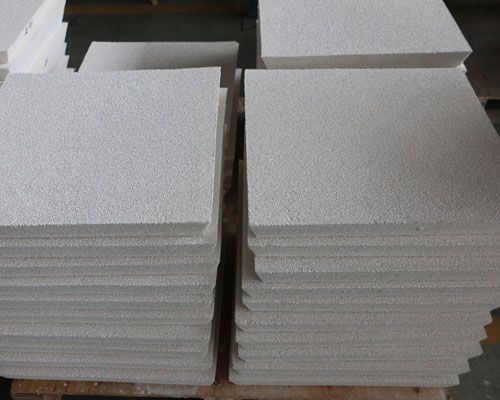
Most plants use square ceramic foam filters because they fit standard filter box designs and distribute flow evenly. Round filters exist, but square is usually easier to seal and replace. The key is tight fit, correct gasketing, and a filter box that prevents bypass. If your current filter box design has uneven seating, that’s often where inclusion spikes come from.
How Do Ceramic Foam Filters Compare to Other Inclusion Control Methods?
Filtration is powerful, but it works best as part of a system. Many high-performing lines combine ceramic foam filters with degassing, fluxing (where appropriate), and a clean transfer path.
| Method | Best For | Limitations | Best Used With |
|---|---|---|---|
| Ceramic foam filter | Nonmetallic inclusions, flow control | Pressure drop, needs preheat | Degassing + clean launder |
| Rotary degassing | Hydrogen removal, inclusion flotation | Doesn’t remove all inclusions alone | Filtration downstream |
| Fluxing | Dross control, cleaning | Can introduce contamination if misapplied | Controlled dosing + filtration |
| Clean launder design | Preventing re-contamination | Requires correct refractory + covers | Integrated transfer system |
This comparison is grounded in aluminum melt treatment best practices and aligns with guidance from the Aluminum Association and foundry process literature. Reference: Aluminum Association technical resources and industry handbooks.
How to Build a Complete Melt Quality Chain?
If you’re asking “how to choose ceramic foam filters,” you’re really asking how to build a repeatable melt quality chain from furnace to mold. In most plants, that chain looks like: furnace/holding → degassing → clean launder → ceramic foam filter → casting. Each step has to be designed to reduce contamination, not just move metal.
AdTech Real case: A Turkish DC Billet Caster That Transformed Quality
In 2022, a DC billet casting plant in Bursa, Turkey, approached AdTech with a stubborn quality problem. Their 6063 and 6005A billet line was running around 22,000 tonnes per year, but they were losing export business because PoDFA inclusion counts were above customer specs. The existing setup relied on older filter boxes with mismatched gasket seating, inconsistent preheat, and a mix of locally sourced ceramic foam filters with variable pore structure.
Our team reviewed the full transfer path—from tilting furnace through the degassing station and into the casting table distribution launder. The biggest issue wasn’t the filter material alone; it was the whole filtration system behaving inconsistently: bypass gaps, uneven metal head, and frequent filter cracking during cold starts.
Working closely with their maintenance and quality teams, AdTech supplied:
- 24 ceramic foam filters (50 PPI, 15″ × 15″) sized for the line’s 6–8 t/h throughput
- A redesigned filter box gasket kit to eliminate bypass and ensure square seating
- Installation and preheat guidance tailored to their existing heating setup, with strict control of ramp rate and soak time
- Ongoing process review over the first three months, including PoDFA trend monitoring and filter changeout optimization
Within two months, the plant saw clear improvements: PoDFA inclusion counts dropped by roughly 45%, scrap related to surface defects fell by about 18%, and the line went from frequent unplanned stops to zero filter-related interruptions through the rest of the year. By early 2023, they had secured the export contract they’d been at risk of losing—and they established a long-term supply relationship with AdTech for ceramic foam filters and related molten aluminum handling components.
That’s the kind of outcome we aim for: not just selling a product, but tightening the whole process so quality becomes stable and predictable.
How to Validate Filter Performance After Installation?
Once the filters are in, don’t just assume they’re working. Good plants validate performance with a few simple checks:
- PoDFA or similar inclusion analysis at defined intervals (e.g., start, mid-campaign, end)
- Visual inspection of cast surface for streaking, cold shuts, or oxide-related defects
- Filter condition check at changeout (look for channeling, cracking, uneven wear)
- Thermal logging across the filter box inlet/outlet to confirm stable temperature and flow
If you see a sudden spike in inclusions, start with the basics: preheat consistency, gasket seating, metal head stability, and filter integrity. Most “bad filter” stories are actually “bad installation or unstable flow” stories.
Where to Get the Right Ceramic Foam Filters for Your Line?
If you’re ready to specify the right ceramic foam filters and build a repeatable filtration process, start with a clear picture of your throughput, alloy range, cleanliness targets, and existing filter box geometry. You can explore our full aluminum casting product range and speak with our team about filter selection, sizing, and integration with degassing and launder systems.
In aluminum casting, small decisions in melt handling show up as big outcomes in scrap, yield, and customer acceptance. Choosing the right ceramic foam filters—and using them the right way—is one of the highest-leverage decisions you can make on any casting line.
FAQ
1. What PPI ceramic foam filter should I use for die casting?
For high-pressure die casting, 10–20 PPI filters work best. They handle high flow rates while removing large inclusions that cause surface defects.
2. How do I know when to replace a ceramic foam filter?
Look for dark discoloration across 70–80% of the filter face, reduced flow rate, or rising pressure drop readings. Any of these signals it’s time to swap in a fresh filter.
3. Can I reuse a ceramic foam filter?
No. Ceramic foam filters are single-use consumables. Once loaded with inclusions, they cannot be cleaned or regenerated effectively.
4. Does the filter need preheating before use?
Yes. Always preheat the filter and filter box to at least 300 °C before introducing molten aluminum. Skipping this step risks thermal shock cracking.
5. What filter material works best for high-magnesium alloys?
Silicon carbide-based filters are recommended for 5xxx series alloys. Magnesium vapor can chemically attack alumina-based filters over time.
6. What happens if the filter is installed backwards?
Flow rate can drop by 30–50%, and filtration efficiency decreases significantly. Always check the directional arrow before installation.
7. How do I prevent metal from leaking around the filter?
Use the correct size ceramic fiber gasket, ensure even compression around the full perimeter, and inspect the filter box seat for warping or damage.
8. What filter size do I need for continuous billet casting?
It depends on your flow rate. As a general rule, calculate required filter area based on your kg/min throughput and target pressure drop using manufacturer flow data.
9. Can ceramic foam filters remove dissolved hydrogen?
No. Filters remove solid and semi-solid inclusions only. For dissolved hydrogen removal, you need an online degassing system upstream of the filter.
10. Why do my filters keep cracking during the first heat?
The most common cause is insufficient or rushed preheating. Follow a gradual preheat schedule—50 °C/hour up to 300 °C, hold, then ramp to operating temperature before metal contact.
Related posts:
 Ceramic Filter for Foundry
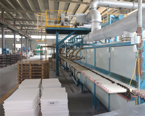 Ceramic Foam Filter Manufacturing Process
 Ceramic Foam Filter
 Ceramic Casting Filters
 Molten Aluminum Ceramic Foam Filter
 Metal Foam Filters
 Molten Metal Filter
 Ceramic Foam Filters Supplier
 Molten Metal CFF
 Ceramic Foam Filter from AdTech
 Ceramic Foam Filters Manufacturer
 Foam Filter Manufacturing Process